After I cut my baffles to size and shape, complete with corners cut for fuel passage, I needed to fill the exposed corners with vinylester and micro so the foam would be sealed off from fuel contact. This was by far the most frustrating task, and took 5 or 6 tries to get right. A few things I discovered during the process:
1. Flox will not work for this.
2. See number one. Instead of trying to prove me wrong, just spend a week standing over your project cursing up a storm (you'll accomplish just as much). Then, use micro and do it right.
3. Micro doesn't work well either.
Honestly, I have no idea how to do this simply and effectively. Sometimes it worked, sometimes it didn't. However (on to actual discoveries):
1. Vinylester, when exposed to the sticky side of duct tape, cures with a thin sticky film. This is not necessarily a problem, provided you can remove the film and still have a sealed corner.
2. Wax paper *must* be removed before vinylester fully cures, or you will be sanding it off.
3. Cling wrap: same story.
Part of why I had so much trouble was that I desperately wanted to do all four corners in one batch, so I was coming up with creative ways to channel micro into all four corners without any spilling out. This was *so* ineffective, I spent a week on it and had to resort to doing one corner per baffle per batch.
As soon as my baffles were sealed, I floxed them into place in the wing. I had a bit of extra flox, so I went ahead and attached my fuel level sender to the tank wall at the same time. I wasn't worried about making the sender removable, since I'd have to do serious damage to the wing in order to replace it anyway.

My next step was to figure out where to put my drain valve. Had I thought a little more about it, I could have easily built a proper sump into this tank; I've done that for the other side. However, this side has no sump at all, so I had to fill it with water and then use a shop vac to suck water out until I could see where the lowest point was. I then popped the bottom out and floxed my drain valve plate in. I had previously drilled and tapped the aluminum plate, and I positioned it as far down in the foam core as possible to give it the best chance of trapping contaminants and water. (picture was taken after lines were run)


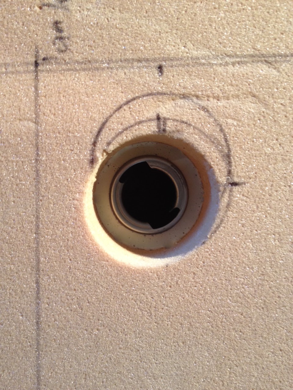
I cut and sanded the top of the tank to shape, used duct tape as a release agent, and floxed it onto the baffles in the same way I did the bottom of the tank. After the flox cured, I removed the top and cut a hole for the filler neck. I'm using a standard 1.5" cam style filler neck, because it's several hundred dollars cheaper than the aircraft version. Also, replacement parts are widely available, as they have been since motorcycles and tractors began using this style filler neck in the who-knows-whens.


I also began running my aluminum lines. The left tank is just a holding/transfer tank, so it only needed a pickup line and a vent/return line. Once the lines were flared/attached/floxed in place (as well as the filler neck), the bottom went back on, this time permanently.

After curing, I filled the tank (as much as I could) with water for a preliminary leak test. After leaving it for half an hour, I saw no evidence of water leaking through the foam cores. I utilized my drain valve to remove the water, then give my tank an extra day in the warm garage to dry out. I noticed a few potential pinholes in one of the side walls, which I promptly spent half an hour deciding whether or not I wanted to fix (with the other option of hoping it wasn't actually a leak presenting a pretty solid case in my head.) While debating with myself, and lamenting that I couldn't pressure test the tank until the top was fixed permanently in place, I came up with a simple way to pressure test spots I wasn't sure about. All it takes is a suction cup. Stick it on, and if it falls off there's a leak. So I picked one up, and started trying my method out. Turns out suction cups won't stick to areas without pinholes, either. The only way I was able to find pinholes was visually. I did find a large number, but patched them without much trouble.
One thing I don't see addressed very clearly is bonding procedures for fueling composite aircraft. As best as I can find, the main concern is that fuel sloshing in composite tanks causes a large amount of static buildup on the surface of the fuel. In order to equalize the charges between the fuel surface and the fueling apparatus, the bonding/grounding strap has to indirectly contact the surface of the fuel. I decided that the aluminum fuel lines, which will be in contact with the surface no matter how much fuel is in the tank, were perfect for bonding. The anodized fittings don't impede the conductivity (surprisingly) so I can just attach a wire to the outside fuel lines and run that wire to a common bonding point.
I also floxed a short piece of fuel line to the top of the tank right next to and visible through the filler neck, which hangs down to the 10 gallon fill level. During the first phase of flight testing, I'll fill the tank to this point to match the 10 gallons the other side holds when full.

Finally, I floxed the top into place.

I blew compressed air through the vent lines periodically while the flox cured to make sure no extra flox clogged my lines.
After allowing a day for curing, I plugged the lines and performed a pressure test on the tank. Naturally, it failed. I believe the flox began curing before the top was fully in place, and I had 4 places air leaked out, all of them at the top of the tank. However, I still had access to all four points, and was able to mix up a runny micro slurry to pour in and around the leak areas. Further testing revealed no leaks, so I removed the wing and set it aside. I'll follow (mostly) the same procedure for the other side.
Continued in Fuel Tanks (Part 3)


