Sunday, November 20, 2016

Engine DISassembly (Part 3)

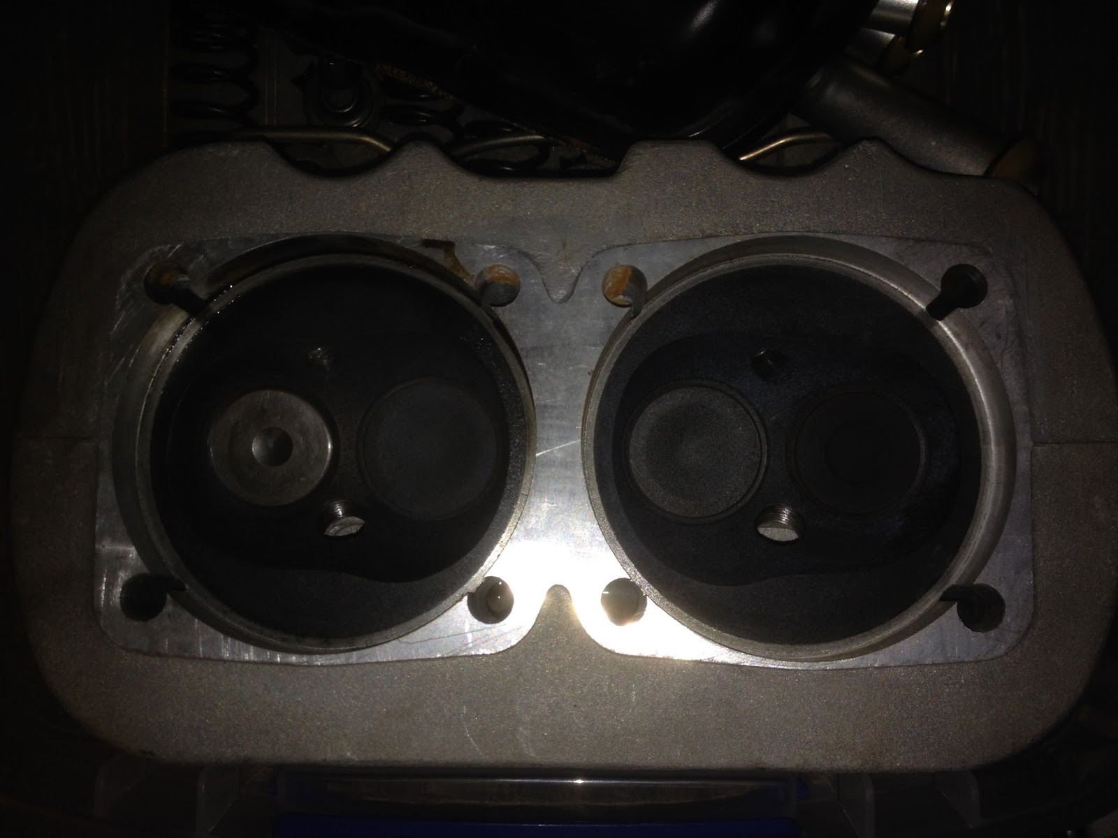
I've been stuck trying to find the right tools for the last week or so, and then trying to find the time, but I finally made some progress. The pictures below show a collar assembly on the front of the motor, behind the prop hub. Apparently this setup is an anomaly - no one I spoke with was able to identify it. There are 4 screws that hold the front collar onto the back collar, which has one screw into each side of the case. Once I got the right size hex key, these came off and the case came apart.


These two collars house an oil seal around the crank shaft where it exits the case. My first inclination is to replace the seal, but I'm not sure what kind of damage I might do removing the prop hub. I'll have to think about it.


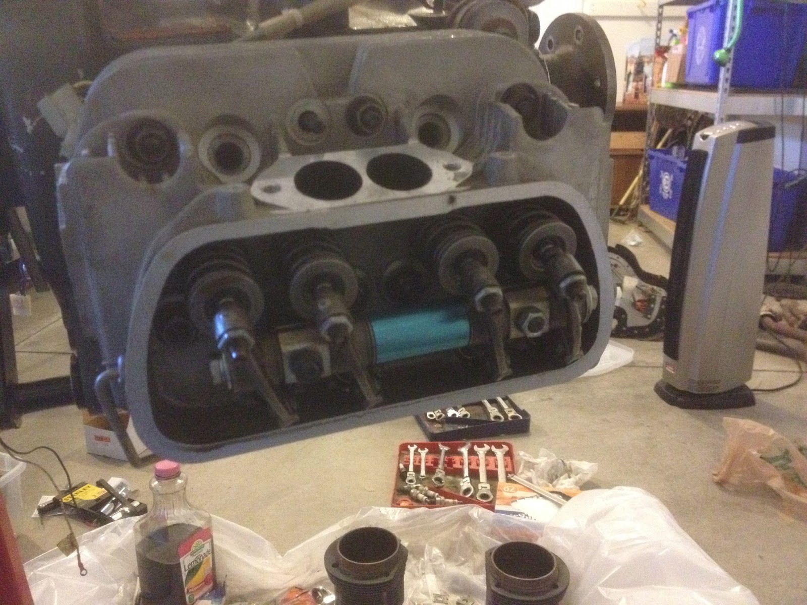
Once the case was split, I pulled all the cam followers and labelled them so I could replace them in the same locations. I'll be taking a lot of pictures once I've cleaned things up, but the camshaft looks like it's in great shape, so that and the followers will probably stay.


The inside of the engine wasn't as pretty a machining job as I'd expected, but everything turned nice and smooth when it was all together, so I'm not too worried about it. I haven't found a reason for the fine metal shavings yet, which makes me uneasy. 


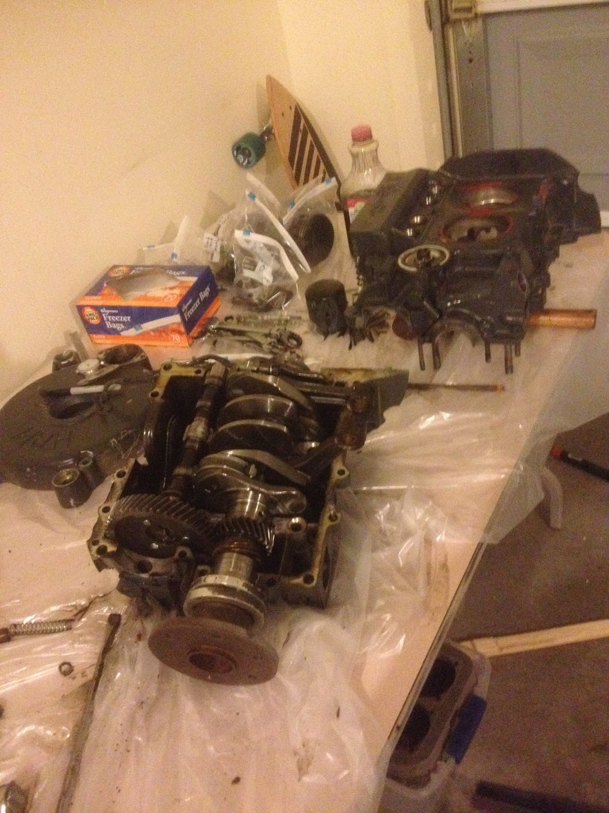
This is where I left it. There are only a couple of things left to do on the case before it can be cleaned up and inspected, and I don't expect the crankshaft assembly will be difficult to take apart. After that I can begin blueprinting, clean and inspect, order my parts, and put this thing back together.


Sunday, November 13, 2016

Engine DISassembly (Part 2)

Not much progress today, but I got a little further. I keep running into bolts that I don't have wrenches for, although hopefully that will stop soon. The main thing I accomplished today was setting up a table to work on, covered in plastic, and transferring the engine block from the stand to my new "workbench."


I got the pistons out, which ended up being easy enough... the Teflon buttons really were just floating in there, but I needed something sharp to stab the sides of the buttons to get enough grip to remove them. I forgot to take pictures of them tonight, but when I get into working on the cylinders I'll be spending about a paragraph on how crummy those buttons are.

Removed cylinders yesterday, but they're all laid out in order here. You can see the lower right cylinder has a lot of corrosion on the outside of it - the other three cylinders aren't corroded much at all. I think the corroded cylinder was a quick replacement to avoid a more serious rebuild earlier in this engine's life.


Another disappointing discovery when I removed the accessory case that covers the flywheel - the teeth are chipped pretty bad on about a quarter of the flywheel. Not messing around with that - I'll have to replace it.... unless they sell just the ring gear for it. I'll look into that...


I also removed the valve springs, and while those all seem to be in good shape, I did notice that the same cylinder with lots of corrosion also has mismatching valves.... the valve on the far left below has almost no carbon deposited, not to mention is shaped different. I'll have to make a decision on whether or not that is an issue/will bother me enough to get new valves.


And here's the part where I don't have a big enough wrench - or rather, big enough socket. Not sure a wrench would be really effective, since this is recessed inside the flywheel.


Tomorrow I'll pick up some more specialty sockets, and hopefully make some more progress on tearing this thing apart. My goal is to have a semi-final list of parts to order by the end of the coming weekend, as I suspect some of the parts will take some time to acquire... especially if I wait until the holiday season.

Saturday, November 12, 2016

Engine DISassembly (Part One)

After a bit of a hiatus, I began tearing down the engine I intend to hang on the front of the plane. I'll be using a 2180 Volkswagen engine, originally built for aircraft use by Hapi a number of years ago. When I received the engine, it was mostly assembled, but I wanted to tear it down, blueprint everything, and rebuild it myself so I know it's done right. Besides, it's hard to powder coat an engine block with stuff attached. So today I finally started yanking stuff off.

Engine on the stand, ready for disassembly:


First I pulled the intake manifolds and spark plugs. I'm working on this engine away from home, so I lack most of my tools and all the helpful things like oil drain pans... Therefore, I used an empty lemonade bottle to catch the old oil. Seemed to work.


I pulled the valve covers, then the valve train. Sure looks a lot simpler than any other engine I've taken apart.


Next step was to pull the head, which came off pretty easily, along with one of the cylinders. The other cylinder wasn't much trouble.


The pushrods and pushrod tubes fell right out as well, and I hung onto those for referencing when I reassemble. I'll probably replace them, along with a good deal of other hardware inside.


The left head valve train was shimmed about .122 off of the head.

The right side wasn't any more difficult than the left. Valve train shimmed .088 on the right side.


I'd have liked to do more, but a little research is in order. The pistons are held on by a large pin, and that pin is usually captured by E-clips or similar devices. Whoever assembled this engine most recently used Teflon blocks that ride against the cylinder wall instead. Nice idea in theory, but if they ever wear down, there wouldn't be anything holding the piston pin in place... which would mean a catastrophic failure. I also noticed that one of the Teflon "buttons" had picked up some debris and scored the cylinder wall with it... another thing that wouldn't happen with the right hardware. I'll have to take some measurements and decide whether I want to hone that cylinder or replace it.

This is where I left off today.


You can see the Teflon "buttons" in the picture below - they're the white circles on the sides of the pistons. I have no idea how to remove these, unless they're to be pressed out with the piston pins. Time for research.


Friday, September 2, 2016

Seats (Part 5)

Continued from Seats (Part 4)
I attached piano hinge to the seat back at the bottom, so I can access the back really easy. While that was curing, I glued in four 5/8" spruce braces for the seat back, to make sure they won't buckle under load. I also cut a 1/4" piece of spruce for the other side of the seat back hinge to attach to.


Once those had set, I cut the seat pan to fit around them, then connected the seat back to the 1/4" spruce with the other half of the hinge. These I lined up with the seat pan in the plane, then epoxied the spruce hinge plate to the seat pan.


Once that had cured, I drilled holes all the way through the seat pan and the spruce hinge plate and epoxied nuts underneath the seat pan, so the hinge can easily be unscrewed from the seat pan. Honestly, that was probably overkill, because it's easiest to pop the whole seat assembly out of the plane and pull the hinge pins. However, it makes me feel better that the hinge is screwed down instead of just epoxied on, and even if the epoxy holding the spruce hinge plate failed, the screws go through that *and* the seat pan, so it's not coming apart unless I want it to. I have a close-up of the hinge and spruce, but it's too blurry to post, so I'll have to take another one.

I went ahead and cut the seat back into two pieces after this was all cured. I didn't cut it before because I wanted to make sure both seat backs were hinged in exactly the same place and direction, so they won't interfere with each other. The last thing I did was seal the edges using 1" fiberglass tape, then sanded them all smooth. I'll probably paint the seat back, but I didn't feel the need to do that yet. With the seats hinging separately, I can use the passenger side as a flat surface when I'm flying solo. The only part that I haven't figured out yet is where to put the seat foam if I do that... but I'm hoping I won't have a reason to need a work surface while I fly. Much of my cross country flying has been done with an instructor in the right seat, which leaves no room for charts in a C172. As a result, I've got a nice kneeboard that will hold a folded chart. I'll be running iFly software on a Nexus 7 on the instrument panel, so in theory the only time I'd need a physical chart would be if my electronics went south, and I probably wouldn't bother moving seat foam and flipping the seat back down in that case.


Sunday, August 28, 2016

Seats (Part 4)

Continued from Seats (Part 3)
I got a call a couple of days ago that my canopy was being molded, so I expect it to be here in the next couple weeks. That reminded me that I hadn't finished my seats yet, which I'll need to help me decide how tall to make the plane. So I started working on the seat back. It's built the same way the seat pan was, and the same way as the wing walks are. But I do have a few pictures of the process.
Here's the second layup:


I build the foam and wood board larger than I'd need, so once the fiberglass was all cured I cut the seat to size. I'll be cutting it in half once the hinges are attached so each side can flip down independent of the other. I'm running out of space in the garage with the wings being worked on, so I had to stick it in place for now.


Continued in Seats (Part 5)

Wing Tips (Part 3)

After hot wire cutting, I did some sanding to smooth it out, as well as making a radius on the bottom edge. I also trimmed away 3/4" of the trailing edge foam and filled it with micro, same as with the wing. After I was happy with the shape, I put two layers of 5.8 oz cloth on the top, two layers on the bottom, and two layers wrapped around the thin edge. The top and bottom layers extend about 6 inches onto the existing wing, and the whole thing is quite stiff and strong. I don't think I'll make any changes to the process for the other side, so I won't bother uploading any new pictures unless something unexpected happens. Here's the (semi) finished product.


Thursday, August 25, 2016

Wing Tips (Part 2)

Once the foam was all glued up, I sanded it down to shape just like the rest of the wing. I ended up with 15" of extra length, and my final airfoil chord at 33.75 inches and right around 0* incidence. Time to make the actual tip.


I'm going to be using a modified Hoerner tip. I used a paper written by Hoerner, as well as the video I linked to in the previous post, to come up with my own hybrid. Hoerner describes and promotes a wingtip that is simply cut at about a 45* angle from bottom to top, which was my original plan. However, in the video uploaded by YouTuber schmleff, his tip changes angles as the wing thickness changes. I'll be using aspects of both, and hopefully not eliminating the good effects of both in the process.

Hoerner tip:


Schmleff tip: (before additional nose shaping)


My adaptation:


Hoerner tip pros: highest L/D ratio without using "tip devices" (i.e. winglets), as a result of vortices around the outside of the wing being pushed out past the wing.

Schmleff tip pros: Higher lift at tips, causing greater roll stability and lowering stall speed

My tips: (in theory?) push vortices past the wing, and give smooth airflow transition to rear of tip where greater lift can be achieved with minimal decrease in top speed, allowing a potentially lower stall speed and therefore slower landing speed.

Enough about theory, here's how it went.

I started by following the schmleff video, taping about 3/8" below the top of the airfoil and 6" inboard of the tip on the bottom of the airfoil. (Wing is upside down in picture.)


I went ahead and cut the foam with the hot wire cutter at this stage, giving me the start of the schmleff tip.


I had a fancy jig planned that would hold the hot wire cutter at the right angle as I moved it over the front of the wing, but I realized since I had this modeled in CAD already, I might as well just plot it on my wing, tape it off, and cut it. Could have done that all at once, but I didn't, so I had to glue back some of the foam I just cut off. The nice thing about hot wire cutting is the pieces fit back on really nice.


Once I had that all taped up, I used the hot wire cutter again, and the general shape was achieved.


I like the way that turned out. All that's left is about 10 minutes of touch-up sanding, and to round the leading edge a little bit, and then I'll be ready to glass it.

Monday, August 22, 2016

Wing Tips (Part 1)

With both wings glassed, it's time for wing tips. I'm doing a version of Hoerner tips, which ought to reduce drag and increase lift by moving the inherent turbulence out past the wing. I did a fair amount of research, and came up with a couple of studies that promoted the Hoerner tip, and a few studies that promoted simple round or rhombus end plates as much better options. I don't like the idea of those end plates, because 1. if they aren't lined up right they'll increase drag, and 2. I don't like how they look. I'm basically following a great Youtube video found here, which details the entire process.

The first step I needed to take was making my wing straight and square on the end. This should have been done by shaping the spars accordingly, but I wasn't smart enough to think about that at the time. As a result, the ends of my wings are pretty wavy.


In order to fix this, I started by cutting an oversized airfoil from a piece of 2" foam, and cut it into a bunch of sections that would follow the angles on the wing endplate.


These were glued on and left to cure. Once they were set, I sanded them to match the rest of the wing.
Next I laid a framing square along my front spar, which is perpendicular to the aircraft's centerline, and used that to draw a line on the top and bottom of the foam 1" outboard of the endplate. After the lines were drawn, I laid some 2" aluminum foil HVAC tape along the lines all the way around the foam.


Once that was lined up and pressed on really well, I fired up my hot wire foam cutter and used the tape as a template. When I was finished, I had a really nice straight, square, flat end plate to glue my wing tip onto.


I'll be extending my wing 15" outboard of the 3/32" plywood endplate, in order to try and squeeze a little better glide rate out of the plane. From what I've been reading, it doesn't seem to have much of a speed penalty, and a number of folks have extended their wing 18" or more this way without adding to the length of the spar. Since the foam I used to fix the wavy endplate issue is 1" outboard of the main spar, I'll add 14" of foam by cutting 7 pieces of 2" stuff and gluing it all together. It's cut to a slightly large airfoil shape to help me get it to the final shape faster. I'm using 3M spray adhesive so that my hot wire foam cutter will be able to slice through it once it's ready, although I'm slightly skeptical about how well that'll hold the foam for sanding.


Continued in Wing Tips (Part 2)