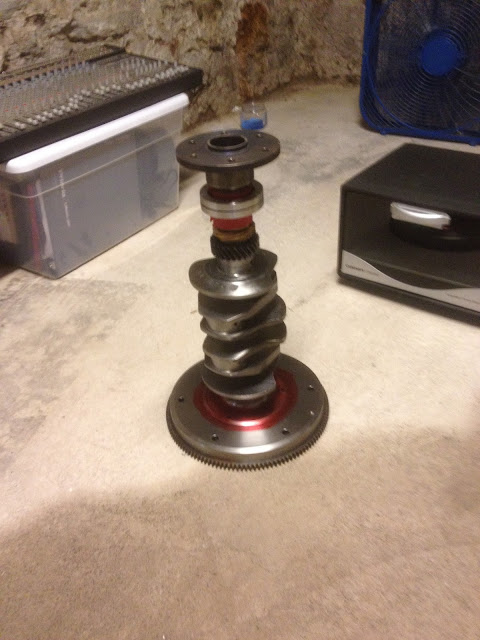
Having a metal lathe, even a small one, is a fantastic way to avoid paying a large amount of money for a small amount of work. I started by chucking up the crankshaft and adjusting until I had less than a thou of runout. That's still too much for bearing work, but I'm not doing bearing work. I put a 45º chamfer on the flywheel mating face, and knocked the burrs off of the pulley hub mating portion of the shaft. A little polishing to make sure the pulley hub slips on, and we're off to the races. The pulley hub was heated to ~400º F, the crank cooled to ~10º F. I still had to use some persuasion with a hammer to seat it fully, but she's on there now.
The two aluminum rings are the replacement seal housing, complete with seal installed. I must've walked through the assembly process a dozen times to make sure I put the seal housing on the correct way, and I still checked it half a dozen times afterwards. The red material is a cut up silicon baking sheet to help keep the rubber on the seal from melting/losing its elasticity.
After I turned the chamfer on the flywheel end, I re-installed the 4 dowel pins. The bottom pin in the picture is larger than the rest, allowing me to index the flywheel. My plan is to mark TDC on the flywheel, since it can only line up one way, and with very tight tolerances.
When I attach the flywheel and snug up the nut, I still end up with about .008" of runout at the edge of the flywheel. Not a lot, but more than I'm willing to put this together with. I used some more PlastiGage between the flywheel and the crank surface to make sure I was fully seating the flywheel... sure enough, I wasn't, and the place where I wasn't touching the crankshaft is the same angle where the flywheel is furthest out. There are four factors at play here; the crankshaft face, the dowel pins, the flywheel face, and the flywheel holes for the dowels. The crankshaft face is most likely true, since that's how it was run successfully before, and my PlastiGage test seems to confirm it. I proved that the flywheel face was true by using a rotary table and a dial indicator and getting less than a thousandth of runout. I think that leaves the dowels. How did that happen?
It happened pretty simply - I used the flywheel to drill the dowel holes. Normally, this would've been the best way to go about it. However, because of that radius on the flywheel that I chamfered the crank to match, the flywheel wasn't sitting quite right on the crankshaft, which means the dowels are *slightly* cocked to one side, which means they *want* to pull the flywheel that way.
So my next step is to torque the flywheel to spec, which is some ridiculous number above 200 ft/lbs, and see if that fixes the problem. If not, I may have to get creative. On a positive note, the only bit of clearancing that I still need to do involves grinding a little material off one of the connecting rods. Once that's complete, I can start setting things out for assembly. I do, however, need to get this flywheel thing straightened out before I can move forward.


No comments:
Post a Comment