Showing posts with label engine. Show all posts

Wednesday, October 10, 2018

Prop Flange Extension

This will be a quick post - as part of my power plant setup, I'll be using a 4" aluminum spacer to help streamline my cowl around the engine. At my place of employment, I've got access to a CNC mill and a larger metal lathe, among other things. I was able to pick up a 5" diameter 6" long piece of 6061 aluminum for about $40 on Ebay, modeled what I wanted in CAD, then went to the manual lathe to turn it. I should have taken more pictures, but I didn't think about it; I do a fair amount of machining at work, and it all feels pretty routine anymore. The first picture I have is after I turned the stock down to final inside and outside dimensions, except for the face that will abut the flywheel. I set it up on a rotary table on the mill to get a bit more precision with the 6 prop-mounting holes, but that was probably overkill.


Spot drill, undersize drill, final drill, chamfer the edges. Not exactly rocket science. I intentionally left about an extra half inch on the end that I chucked up for the majority of the turning work, so that the marks left by the chuck wouldn't be on the final part. When I reversed it to turn the remaining face, I used some orange .050" plastic shim stock between the jaws and the part to avoid marring the finished surface. Turning the remaining face was straightforward, though I took light cuts to make sure I wouldn't pull the part out of the chuck. 


After the final lathe operation, I drilled the other 6 holes and cleaned up the part. Nothing left to do but put it away until the engine is ready to run... except test fit it on the flywheel.


Wednesday, August 15, 2018

Whoops... This is a new problem!

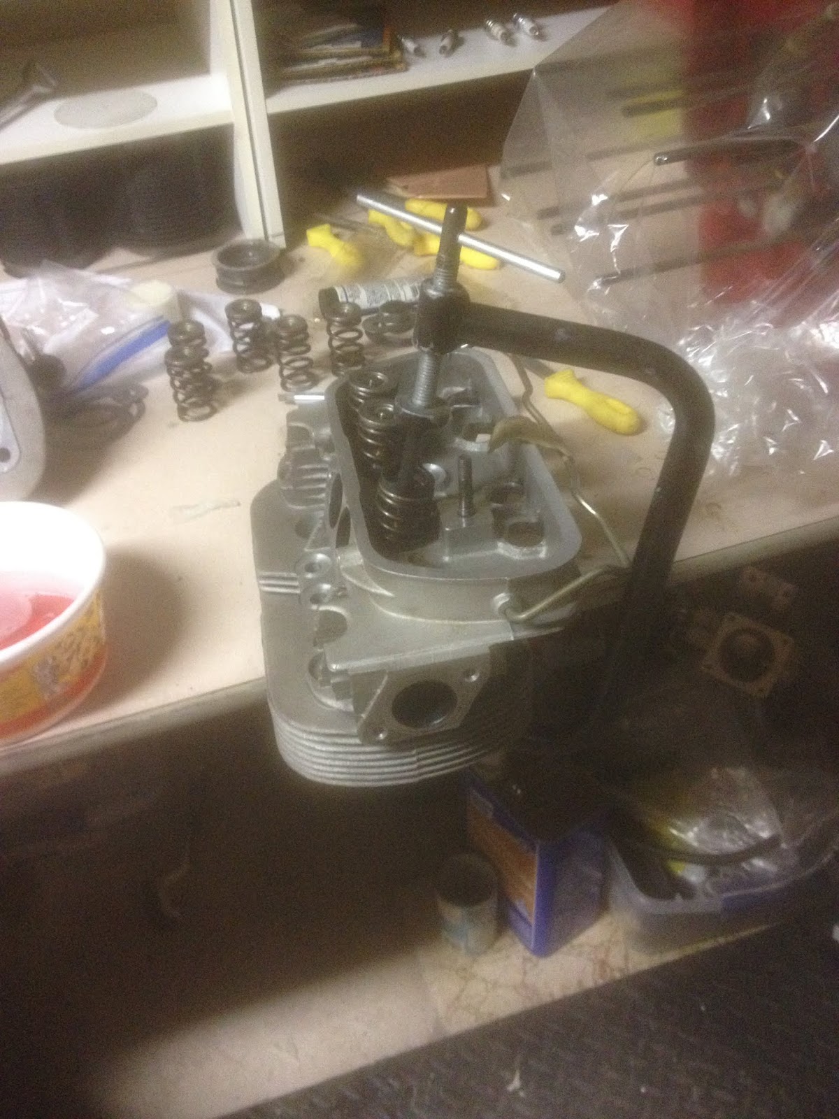
Ok, ok, it's not really a problem... at least, it's not a mistake or a roadblock or a money pit kind of problem. The last few weeks have been pretty good - I finished assembling my heads,


made a plate for bolting the cylinders on to check deck height for each piston/cylinder set,


(btw, this gave me wacky results - I had to remake the plate to cover *both* cylinders at once, the same way the head will when the engine is assembled)


(Again, not like this.) and then made a new two-cylinder capturing plate and measured deck height at final torque.

Deck heights were all pretty darn close - I had a spread of 0.1997", 0.122", 0.1225", 0.125". Because I have a lathe handy, I was planning on chucking up the pistons and dusting them all perfect - but after doing the math, I realized that by arranging the heads correctly, my compression ratio would range from 7.976:1 to 8.021:1. In other words, a maximum difference of 0.045:1......... I think that's close enough!

I went ahead and painted the cylinder numbers on the case according to convention, and then marked the cylinders and pistons accordingly.


Since I wanted the heads on certain sides, I went ahead and marked them as well.


The last thing I have to do on the engine for now is bag everything up - each head will get a bag, each piston/cylinder will get a bag, and the block will get a bag. I don't want to have to carry the assembled engine up out of the basement when we move in a few months, so I'll just leave it in pieces until it's in a shop that's on the ground floor. After that, I'll assemble it and bag it again, until I need to take more measurements off it or am ready to attach it to an airplane. So what's the problem, you ask? Well, this engine has been about the only thing I can do related to my plane right now. Every couple weeks we travel to see the rest of my family, and I can sneak away for a few hours to work on the plane when we're there, but otherwise it's just me and the engine. Now that I'm mostly done with that, I'm not sure how I'll keep making progress... and if I'm not making progress, I'll drive my wife over the edge. :)

Saturday, October 21, 2017

No turning back now...

Got my LocTite, and had a few free hours tonight, so I finished the crankshaft buildup by torquing the connecting rods to spec. Then I gooped up all of the head studs with Permatex Aviation 3H and installed those in the case halves. 


I got everything covered in moly grease, dropped in the cam lifters, crankshaft, camshaft, cam plug, and stud seals, then put the case together and torqued everything down just as if I was sealing up the case for real. 


I checked free rotation the whole way through, and man, is it nice and smooth. All the gears mesh up just fine, no weird noises or rough spots. With that, there was nothing left to do but tear it all down so I could add grease and sealer and put it back together one final time!


Got moly grease on the cam lifters, which in my case are hydraulic. Using moly on them really helped them stay in place; a big plus on aircooled VWs, since they want to fall out when you try to put the case halves together. Dropped in the crank and camshaft, then gooped up the cam plug with 3H and stuck that in its place. (Apparently this picture was actually before the cam plug was installed.)


Next came the excitement - spread 3H on the other case half, mate them together, and put all the nuts and bolts in.


I gave it one more free rotation check once everything was torqued and ready to leave, and sure enough - smooth as you please. I'm gonna have to find something else to complain about now that the crankshaft is doing what it's supposed to do. One final thing I did before I sealed the case up was check my end play at the flywheel. I've got three shims in between the first bearing and the crankshaft to act as a thrust bearing, and the remaining end play is shown below. I think I'm supposed to have it at around 0.005", but I'll have to check on that. I'll order a shim to put between the flywheel and the first bearing and call it good.


Wednesday, October 18, 2017

Crank Buildup... Again.


So, when I said earlier that the case was "torqued to spec" and that the crankshaft "didn't bind...." Turns out I lied. I didn't have two nuts on... and it turns out that those two little nuts caused a big problem.  Once I had *all* of the hardware on and torqued, the crankshaft stuck... pretty bad! I ended up doing a lot of digging, and it turns out that the piece that used to be the prop hub, which still provides a bearing surface, was the problem.

I started by trying different clocking orientations - pulling the hub, heating it up, rotating it slightly, and putting it back on - and I did find one position that was very close to perfect. However, it still had a sticking spot, and when I put a dial indicator on it, I could see why - while the hub was only out of concentric by about .0003, there was a single spot, like a lobe, that was more than a thousandth of an inch high. Now, I have a lathe, but I'm not confident enough in my abilities to do serious engine work. Nevertheless, I'm not willing to pay a machine shop another hundred to polish a single bearing surface into spec. 

So I chucked the crank into the lathe and set up to knock the lobe down with some emery cloth held in my tool holder, so I could just hit the high spot.


Once I thought I'd gotten close, I used some medium and then fine emery cloth to get all of the tooling marks off. Then I pulled the whole thing off the lathe and assembled and torqued the engine to spec again.


..........??????!!!!!!!!!!!!!!!!!!!!!!!

Rotates freely. Smooth as can be. I was pretty excited! It's still got contact across the whole bearing, too, so I didn't just turn it down so far it doesn't touch anything. (To give you an idea, I think I took about half a thou off of the bearing before I started with the emery cloth... so really, very long process for a very small amount of material.)

I cleaned the crankshaft up, re-lubed the connecting rods, and started to assemble them. Unfortunately, I can't find my LocTite to save my life. I think I left it in PA when I used it on my landing gear.


Yes, the connecting rods are pointing in wrong directions - that's just so the nuts are easy to get to. I couldn't just leave it all like that, so I went ahead and worked on setting up the distributor assembly. Because of the type of distributor I have, I don't think the orientation of the distributor drive shaft matters in the least. However, just in case I'm wrong, I oriented everything the way the book says to, marked it with red dykem, and put a holding screw in place to keep the distributor aligned correctly. I've gotta get a couple of new screws for that, though... these two are looking pretty buggered up.


I intend to assemble the crankshaft, then install it and the camshaft into the case, along with the correct end play shims on the flywheel, torque the case to spec and check free rotation one more time before the final assembly. If it all checks out, then I'll install the lifters, cam plug, and whatever else I'm forgetting, then put sealant on the case and bolt it all up for good. There's still a lot left to do, but this feels like a big turning point in this whole process.

Sunday, August 27, 2017

Fit so nice, I made it twice....

Actually, it was the wrong material, so I kicked myself a few times and bought a new flywheel. This time, a *forged* flywheel, not a *cast* flywheel. Had I the sense to do more research ahead of time, I'd have only made it once. Nonetheless, the new version is around 300% *less* likely to break apart during flight.

That's version 2. Same dimensions, but machines a lot more like 4130 than the first one.


In this blurry picture I'm pointing out the locating step for the flexplate. That way I know it's concentric. I did the same on the inside for the prop extension:


Now that this is finished, I was able to start test assembling the crankcase. First, the connecting rods on the crankshaft:


Drop the crank assembly into the case and add some nuts, torqued to spec:


It still rotated freely after it was torqued, so that was a good sign. No rubbing or clearance issues so far. The next step was to add the head studs and check the piston deck height. I painted my head studs to help avoid corrosion:


And then I added them to the pile.


I added a cylinder and piston, and started taking measurements. I used a .030" shim under the cylinder, which is how the engine came to me. I set up my dial indicator and rotated the crank to TDC for that cylinder.


Zero'd up the dial indicator (though the photo makes it look off);


Using a piece of steel rod I had laying around as a straightedge, I measure deck clearance + rod width at 0.428" or so.


The rod I used measured 0.314", which means my clearance distance is 0.114". That's a lot more than I want! VW specs are between 0.040" and 0.080". I went back and checked, and the old pistons are the same as the new ones, and the old cylinders were within a couple thousandths of the new ones. That means that this engine was assembled wildly out of spec.... which shouldn't be a surprise, but it was. And means more work; removing the shims brings me down to 0.084", which is out of spec (and 0.024" more than I really want.) That means I'll have to chuck each cylinder up on the lathe and turn it down to what I want. 

Unless...

...unless the heads are also anomalies, and have a much smaller chamber than normal heads, in which case the cylinders need to be extra long.... Bottom line, the new priority is get the heads reconditioned and blueprinted so I know what kind of setup I need.

There has been nothing straightforward about this engine. Armed with the knowledge I've gained from this process, I believe the next engine I assemble will be from brand new parts that I know the details on.

Monday, July 3, 2017

Dowels are hard, PlastiGauge is soft.

It took a lot of work, but I got all four dowel pins out without damaging the crank. The two I put in came out easily enough with some vise grips and a bit of twisting and pulling... the two that were in from before were another story entirely. Nothing would touch them, including the hardened jaws of a *nice* set of vise grips. (Those are no longer a nice set of vise grips, by the way.) In the end, I discovered why machinists have drill bit sets up to half an inch with just a couple thou of difference all the way up...

...It's because hardened steel pins can't be drilled out with big steps between bit sizes! It took me a solid hour and a half to drill each pin out. However, both of them twisted out right before I broke through the wall of the pin (after a couple good taps with a hammer on the side of the pin to break it up a bit.)

I checked the face on a dial indicator, and at most it's out a single thousandth at the edge. That's about an inch from center, which means that might account for about 5 thousandths at the edge of the flywheel.... which means something else is amiss. I checked the flywheel by placing it on an indexer, supported by placing a tight tolerance block between the indexer and the mating face on the flywheel. Spin the indexer, check for runout.... I forget what I got, but it was insignificant (which is why I forgot it. :D) I was pretty puzzled at that point. However, since the pins were out of the crank, I was able to rotate the flywheel on the crank. How does that help us? Well, before I pulled the dowels, I'd marked on the flywheel exactly *where* the runout was, as well as *how much.* When I put the flywheel back on after the pins were out, I lined it up pretty close to where it was originally... and got pretty much the same results. (I didn't use an indicator, as I was less interested in how much it was out as *where* it was out.... and it was wobbling pretty obviously.) Ok, repeatability, that's good. So I rotated the flywheel 180 degrees and tried again. If it was the flywheel, that should've made no difference; the marks on the flywheel still should have been correct. If it was the crank face that was out, then the marks on the flywheel should have been exactly (or close to) opposite what the flywheel was showing the second time around.

So what did I find? Well.... actually, it was about 70 degrees off from where it was originally. I didn't know what to make of that, until I started taking careful measurements of everything. What I found was that the flywheel had a bit of a radius where it mated with the crankshaft, and the crankshaft did not have that radius. I think what's happening is that there's a tiny bit of play between the *side walls* of the flywheel and the crankshaft, and the radius causes the face of the flywheel to be tighter than the crankshaft can fit into. Add the radius and a little bit of slop and, unless the radius on the flywheel and the edge on the crankshaft are perfectly uniform and smooth, odds are the flywheel just isn't seating fully and is staying at a bit of an angle. The fix is simple; just cut a matching radius (or, much easier, a slightly relieved chamfer) on the crankshaft. The side walls and dowel pins will still locate the flywheel, and the face where the two meet won't lose much area. I like that idea better than cutting a sharp corner into the flywheel. 

I should mention, the reason that this is an easy fix is because I recently picked up a Jet 9x20 metal lathe. Just as soon as I finish getting that set up in the basement, this will be a pretty straightforward job. I'll be spending my evenings this week cleaning it up and, as soon as my insert tooling shows up next week, I'll be making chips and breaking tools. Also touching up airplane engine parts. 

I also got my oil galley plugs straked in place so they can't rotate out. I found one of my case savers was loose, so I used some red LocTite, filed a notch in it, and straked that in place as well. 

The last thing I wanted to do today was check my connecting rod bearing clearance. If you've never heard of PlastiGauge, you're in good company; none of the auto parts stores I went to had ever heard of it either. I ended up at a local NAPA, a company I spent 6 years working as a counterman for, and gave the kid at the counter the part number I remembered as being correct. "Huh, it says we've got 12 in stock. What is it again?" It comes from the warehouse packaged as a dozen, so I guess it shouldn't surprise me he'd never heard of it; he'd never sold any of it. Anyways, PlastiGauge is a kind of plastic-y wax string that's very precisely formed. A strip of it is placed between two surfaces you want to check clearance on, and those two surfaces are brought together however they will be brought together during final assembly. In this case, those surfaces are the connecting rods with bearings installed, and the crankshaft. Blurry picture, but the green little stripe in the middle of the white grease is the PlastiGauge before the con rod is tightened....


...And after:


The lighting was pretty awful. However, I can tell you that the strip of green that's *not* a weird reflection is the one above the .0015" mark. Basically, that wax gets squished to different widths based on how much clearance is available, and the package the wax comes in has a gauge on the side to check it with. All four journals had *exactly* the same width as the .0015" mark, and they were all very even stripes from one side of the journal to the other. (If the journals or the con rods had any taper, that would've shown up as a tapered stripe.) The specs for this engine are 0.0008-0.0025, so I'm smack in the middle of where I want to be. Any wear is going to cause that clearance to open up, and I've got a solid thousandth of an inch for it to open up before I make it out of the range I want to be in.

I'll putz around with little things here and there, but mainly I'll be setting up that lathe and taking some test cuts to get to know it. I've got to do my touch up on the crankshaft, and a couple other things, and then I can start test assembling everything. 

Sunday, June 18, 2017

MORE Case and Crank prep...

It's been slow going lately, but progress seems to be taking place. I got lost in a lot of thought experiments and what-ifs, and (as is usually the case,) ended up right back where I started. So I cut the top off of the flywheel flange on the case, did a little bit of clearing on the inside of the case (some spots didn't seem to have more than a few thou of room for rotating parts), and used a Dremel to carve away a couple of channels for the engine mount in the back.


I also pulled all the aluminum plugs to get an idea of how much stuff was trapped in the case...


...And there was a lot! Much of that was from walnut blasting the case, but I found a good number of metal shavings as well. I'm glad I pulled the plugs... Next I tapped the holes for various pipe thread plugs, ranging from 1/16" NPT up to 3/8" NPT. I used a 1/2" NPT to tap a larger hole in the front for an oil temp sensor, because I've read bad things about the current temp sensor location (near the flywheel end of the case) actually reading quite a bit lower as a result of not being in a high-flow area. The new place is directly in the oil flow as it enters the oil pump, so it'd be hard to get a better reading than that!

Drilling and tapping the magnesium was quite easy, actually... in that the magnesium tapped without much force. There were a few places that I had to tap a few threads, then grind the tap down, then tap a few more, then grind, back and forth a few more times until the plug fit the way I wanted it to. There's one hole that I may have tapped just a little too hard and began to mess up the threads, but the plug threads in just fine and seems to have full contact along the entire length and circumference of the plug, so I'm going to leave it.

Now that all of the holes are prepped, I'll pull all the plugs out for another cleaning session. The last step will be to file a notch in each of the plugs so I can swage the case metal into those notches as a final insurance against the plugs working their way back out.


I forgot to take pictures, but I drilled the crankshaft for a couple more dowel pins. When I received it, it only had two, which was probably fine running the prop off the other end, but I'm not comfortable only using two running it with the prop hanging off the flywheel. So I drilled two more holes, reamed them, and tried to put the dowels in.... oops! One of the holes is *way* too loose! So I ordered a 11/32" drill bit blank, cut it down to the right length to be a dowel pin, and re-reamed the hole to be a press fit. This really isn't a bad plan anyway, as it keeps my flywheel aligned the same way every time it's reassembled, and the only extra work I'd have to do on a new flywheel is drill one hole slightly larger.

Upon reassembly of the flywheel and crank, I realized the flywheel is running about 60 thousandths out of true at the outermost edge. Not cool at all. So my next step is to remove the dowels and see if the crank face is out, but my bet is that somewhere along the way some burrs crept up and are keeping the crank from seating correctly. At least, I hope that's what happened... otherwise it's back to the machine shop.

Monday, April 10, 2017

Starting to prep for assembly.... sort of.

With my crankshaft back and polished, I was able to begin reassembling the gears onto the nose.  First the key:


Heat up the cam drive gear, and slip it on:


Next the spacer and the new brass distributor gear.


I'm working out the best way to attach the prop hub - I know what orientation, but if I want it repeatable to exactly the same spot, I'll need to build some kind of jig that locates off of the cam drive gear. I'm not sure how much that will matter at this point.

In the meantime, I finished walnut blasting the case, and decided to try it on the heads as well. They were somewhat improved, but I'll still try soaking them in carb cleaner to try and get rid of more of the carbon that's built up. Ignore the ape blocking part of the picture...


And below, a chamber in progress to show my future self that it was, in fact, having an effect:


Once everything was sufficiently blasted, I used Simple Green to clean the case as best I could. I'll admit, I focused a little more on the outside than the inside, but I think it's pretty clean all the way through.


Once clean and dry, I cleaned the outside with solvent and got ready to paint. Bob Hoover says three things about painting the case: Do it, do it black, and do it thin. When I got the case, it was painted a dark gray... over top of a dark blue. Two layers of paint, the outer one fairly thick, were definitely not going to help much with thermal transfer, and yet it still flew that way. In light of that fact, I took Bob Hoover's advice on two of the points: I painted it, and I painted it thin.... and I painted it red.


I figure the color is less important than the paint thickness, so I cut the paint with Naptha and brushed it on, making sure to run the brush over any areas that looked like they had extra paint. The end result is definitely brush-textured, and not exactly what I had envisioned, but it looks pretty nifty all the same... and more importantly, it's protected from corrosion and it's not likely to overheat from the paint. I'll put this in the oven like I did the cylinders to get the paint nice and hard... it makes a big difference!

Friday, March 31, 2017

Good news! (And also, electronics are finicky!)

Just a quick pseudo-celebratory post - all of the work I've been doing on this engine has been under the shadow of uncertainty. The engine was involved in an off-airport landing, and I've been wondering if my crankshaft had sustained any damage. If it had, this engine would probably be scrap, based on how it had been modified - the major modified parts just don't seem to be readily available, and other manufacturer's modified parts wouldn't fit, and that would mean I'd need a new crankshaft, prop hub, and engine case, and they'd all have to be machined... Got it back from the machine shop today with a clean bill of health. Now I just have to finish cleaning and painting a few things, and the reassembly can begin.

In other news, apparently circuit design is a little tougher than I thought... received the PCB I had printed for my landing lights, (they look FANTASTIC, by the way - really like the purple solder mask with the gold solder pads) soldered everything in place, and... nothing. Back to the drawing board...


Tuesday, March 28, 2017

Rust removal sucks, Cleaning sucks, Painting sucks...

....but they're all pretty necessary if this engine is going to last. So I've been doing due diligence to remove corrosion, clean up, prep, paint, and heat treat all my engine components according to best practices as instructed by Bob Hoover and Tom Wilson. There's a fantastic resource online at http://www.eaa691.net/images/pdf/VW%20aircraft%20engine%20building.pdf , which is a hundred some pages on what to do, why to do it, and what happens when you don't. I've been just collecting parts and trying to get everything ready for the first trial assembly. Tomorrow I'm taking my crankshaft in to have it magnafluxed, and if it comes back ok I'll start putting stuff back on it. First the woodruff key and the gears, then the prop hub. The next step will be installing the bearings in the crank case, and dropping crank and camshaft, along with some associated hardware, inside and making sure it all turns the way I want it to. 

I got new cylinders and pistons, measured them, weighed them, cleaned them *very* well, and painted them black to prevent corrosion and encourage heat transfer. 

The cylinder on the left has wet paint on it, the cylinder on the right has been cleaned but not painted yet. I made sure to keep track of the cylinders, and marked them after they were painted so I could keep track of them.


As it turns out, the cylinders I designated as "A" and "D" were both 4.490" between the two sealing surfaces, whereas cylinders "B" and "C" were slightly shorter at 4.487". That's right on the edge of too much difference, but because I've got less than a half a thousandth of difference between matching cylinders, I'm not going to send them out to have them machined. Instead, I'll put both of the "long" cylinders on one side, so the heads will be able to seal correctly, and either make up the difference between the two sides with a .003 shim, or just not worry about it.... for all I know, once it's assembled, other tolerances may stack up and either make it a larger difference or even it out. That's why I'm calling this a "trial" assembly, because there may be adjustments to make after it's all together. 

I'm working on removing some surface rust on my prop hub with vinegar. Most of it came off after soaking for about two hours, but I'll give it another shot tomorrow after work. I still have a fair amount of cleaning to do on the engine case, which is about the last thing I want to do... but it's going to be the thing that's holding me up in just a few days, I think. By next week, I hope to be posting pictures of a freshly painted, partially assembled engine.