Wednesday, August 17, 2016

Outer Wings (Part 5)

I started by sanding down the foam I glued on yesterday to fix the low spot. Once that was sanded to contour, I went ahead and sanded the trailing edge to contour as well. I was a little pressed for time, otherwise I would have finished sanding and gotten ready to glass. I did have time to mix up some more micro, though, so I poured/squeegeed/scraped it into place to finish filling in the low spot. After sanding:


And after adding micro, it's nice and smooth and follows the airfoil perfectly.


I also had time to use a wire wheel in a power drill to scrape away the foam within about 3/4" of the trailing edge, and filled that with micro for strength. I did this on the other wing as well, and it's crazy stiff and crazy strong now.


I have to hand plane the spars down a little so they don't stick out, then sand the leading edge and prep it for two more overlapping layers of fiberglass. I also need to cut and attach some prepreg FG strips over the WAFs so I don't lose a ton of vinylester down those cut-outs. After that, I'll be ready to glass the bottom of the wing, then move on to the wing tips.
Continued in Outer Wings (Part 6)

Pitot (Prandtl) Tube

Let me start off by saying, it's probably much easier to just buy a pitot tube. But one of my major motivations for a wide variety of my hobbies is the voice in my head that says, "I can do that, and I can probably do it better*." So in the spirit of not accepting the status quo, I decided to see if I could make my own without buying any new tools.

Let me also explain that a wide variety of homebuilt aircraft builders find inexpensive ways around all sorts of problems, and this is one I've seen a lot of creativity with. From just soft aluminum tubing to VW pushrods to all manner of "I had this laying around the house" DIY, it's been proven that with a little trial and error, you can make almost anything work if you try hard enough. However, due to the speed at which this plane travels, and the amount of trouble I would be in if my airspeed indicator decided to stop working due to a bent/broken pitot tube, I felt it a worthwhile pursuit to build a very sturdy, very likely to be accurate structure. I didn't design anything new, just copied other designs that made sense to me, focusing first on strength and second on aerodynamics. With that out of the way, here's what I did.

I determined that 2024 aluminum was a good material to use, as it's quite strong and still quite light. Also, because it's "just aluminum," I was willing to try turning it on my wood lathe. I've turned wood for about 7 years, which certainly doesn't make me an expert, but I've had the pleasure of playing with a lot of different species. Aluminum is much easier to turn than many of them. It takes much longer to shape, but there's no grain to it, so I had no troubles turning it with even my cheap lathe chisels. I started with a 3/8" rod, cut it to length, trued up the ends in the lathe, then drilled a 3/16" hole through it, and finally turned one end to a point. This would have worked fine, but...

One of the difficulties with an airplane is, you're moving through the air. The difficulty comes in figuring out just how far away the ground is. We know that, as a general rule, air is less dense the higher we are. The altimeter in an airplane counts on that fact to display its altitude. An altimeter measures air density by measuring air pressure, but where do you take that measurement? Inside the airplane isn't a safe bet, as air currents can vary wildly and cause massive pressure shifts depending on airspeed, air vents, and where you put your flight bag. Outside the airplane, the air is moving very rapidly, and if the static air source is tipped slightly into *or* slightly away from the direction of airflow, your reading will be very very wrong. One of the more common methods is to place your static source, or port, on the side of the fuselage, where the port will be perfectly perpendicular to the airflow. If you fly the airplane in a slip or skid, however, your measurement will be off again, so you need another port on the other side of the plane so the measurements can even out. One of the more elegant solutions to this is called a Prandtl tube.

A Prandtl tube combines the functions of a pitot tube and a static port, and does so in a way that, theoretically, is less prone to error under normal conditions. Do other methods work? Just fine, as a matter of fact. However, for this airframe, a number of people have used a number of methods, and it seems that what works for this guy causes major problems for the next guy. A Prandtl tube should work on any airframe, as long as it's placed in a free airstream. I stole a diagram from Wikipedia:


Pitot and static, measured from the same spot. How to accomplish this with minimal effort?

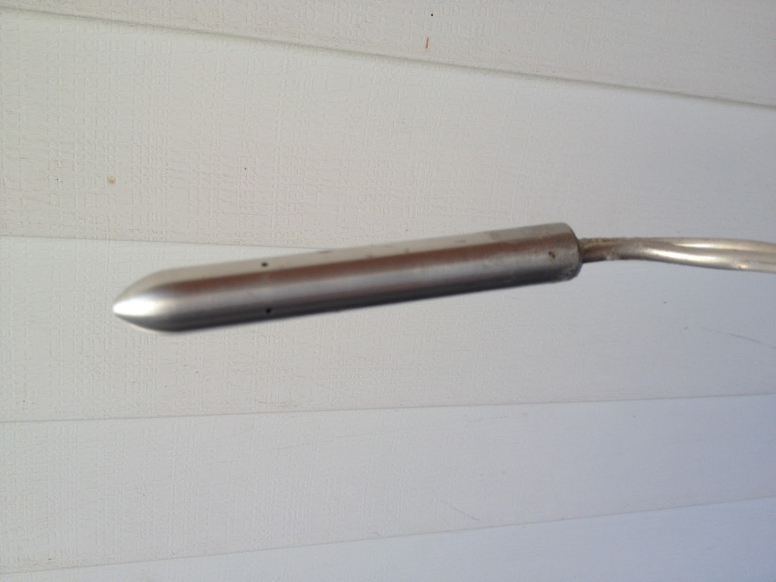
First, I got a 5/8" 2024 aluminum rod and turned the shape. Next, I drilled it down the center with three drill bits: 1/8" bit from the front straight back about an inch, 3/16" bit from the back all the way to the start of the 1/8" hole, and 3/8" from the back about an inch shallower than the 3/16" bit.


Next, I drilled 4 1/16" holes about 2 inches back from the tip, each 90* from each other, so I ended up with a hole in the top, bottom, and each side of the tube. I then took some 3/16" OD aluminum 3003 soft tubing I had laying around (after quite accidentally ordering 25 feet of the wrong size) and floxed a piece all the way down into the 3/16" hole, and then floxed another piece about an inch inside the large hole, then used more flox to seal the large chamber. What I ended up with looks about like this:


The red is the tubing, the green is the flox. Only two of the 4 holes are shown. Once that all cured, I hooked it up to my airspeed indicator and altimeter and took a drive, holding the Prandtl tube out the window. It seemed to work poorly, until i disconnected the altimeter. Turns out the altimeter leaks like a sieve, but the Prandtl tube works like a charm. I was getting very consistent readings, even angling the tube 15 degrees or so from straight on into the wind.


Ok, so it works. Now all I had to do was build a strut to hold it ~4" below the leading edge of the wing. To accomplish that, and because I was feeling picky, I printed off a low drag NACA airfoil (NACA 0021, I believe) and cut out two wood templates, glued them onto a piece of foam, and sanded that foam to shape. Then I glassed the foam, drilled a few holes to attach the Prandtl tube and to allow the two 3/16" tubes to run up the center of the foam, and glassed that all together.


After it had all cured, I put on a couple more layers of micro, building up the trailing edge, fairing in the transition between strut and Prandtl, and then sanded it nice and smooth. It'll stay that way until I'm ready to attach it to the plane. (Obviously the last picture is not sanded smooth. I'll update this with another picture once it's finished and attached.)


*Better, more often than not, means good enough for less money, or better for my specific application. If I really thought everything I did was better, I'd be a businessman (and probably a very, very broke one at that.)

Tuesday, August 16, 2016

Outer Wings (Part 4)

Continued from Outer Wings (Part 3)
With the plane upside down and wing reattached, I began by cutting the rest of my foam pieces to shape. It was during this process I realized that, during my fuel tank construction, I glued the bottom center section of foam incorrectly. By incorrectly, I mean that the foam was actually recessed below the airfoil shape for about half a square foot. I had problems fixing similar trouble spots before, but I've decided to try a different method with this area. I didn't take a before pic, but the after pic gives the general idea. The darker area is the low spot.


I decided to go ahead and sand the center section to the airfoil shape so I would have a solid understanding of where the foam was low. After that was accomplished, I traced and cut out a piece of foam 3/8" thick that was 3" smaller around the edges than the space that was low, and I glued that on. My next step will be to sand that to shape, then use micro to fill the outer band of the low spot, utilizing a straightedge while the micro is still wet to get a nice flat surface. This should work much better than my previous attempts, which were to glue foam over all of the low spot and sand it away. The problem was that the micro didn't sand as readily as the foam, and created high spots. 

With that figured out, I turned my attention back to adding foam over the rest of the bottom of the wing. Pretty straightforward, just make sure there's enough foam sticking up to sand away, and enough foam left after sanding that it won't flex after fiberglassing.


I came up with a simple (sort of) way to help hold long pieces of foam in place when they want to sag. First I cut off a piece of string about twice the length of the foam. Next I poked holes every foot or so in the foam I want to attach. The string gets secured at each end, by whatever means necessary. Finally, the string gets pushed up through each of the holes, then pulled until there's no slack. When you're finished, you've got plenty of string loops to help rearrange or secure your foam. I didn't end up using them to hold the foam in place, but they were very helpful for making small adjustments while the micro cured.

Top side:


Bottom side:

Sunday, August 14, 2016

Outer Wings (Part 3)

On the left wing, I tried to modify the plans method to make it easier on myself. I cut out foam nose ribs that, rather than stick all the way out to the leading edge, only stuck out far enough to support the foam planks. Unfortunately, they weren't quite right, and it caused a lot of headache and frustration trying to rip out and replace foam. So this time, I did it a little closer to the plans method. Glued foam nose ribs in place, but then sanded them to the airfoil contour before adding the rest of the foam. It worked quite well, and was much easier than trying to work out the geometry of the nose supports changing size, length from the spar, and angle changes for washout.


Foam planks being cut and placed:


Once in place, I began the arduous sanding process yet again.


Honestly, it only took a couple hours, including frequent hydration (read: lost motivation) breaks and several "Is there *any* other way that would be *slightly* better?" pauses. One of those gave me the idea to cut slits along the entire length of my aluminum angle sanding block, and use that edge as a saw. It worked fairly well for large chunk removal, as long as you were careful not to cut too close to the final shape.


Eventually, I did manage to finish sanding the top of the wing (although not perfect - thank goodness for micro!) and got ready for another round of glassing. It's been so hot, I've been getting all of my supplies ready and all of the prep work done in the evening so I can get up early and finish glassing before 9 or 10 AM. Any later and the vinylester just sets up too fast. One interesting thing with vinylester that seems different than any other two-part system I've used - if the vinylester is gelling, and I'm not quite ready for it to set, I can actually add a little extra time by adding a little more vinylester (with hardener added, of course.) Not sure how or why, but it's saved me from a lot of repair work a couple of times.

I didn't get any pictures of the process, but it went like this:
Step one: micro from the front spar back to the trailing edge (skipping the spars)
Step two: lay one layer of 5.8 oz cloth and one layer of 1.5 oz cloth on the micro'd area, wet out completely
Step three: micro from the front spar forward and underneath, two inches past the chord line
Step four: wet out two layers of 5.8 oz cloth on a piece of 2 mil plastic, then lay the cloth in place on the leading edge of the wing. Much, much easier to do one layer at a time, otherwise you risk wrinkles in the bottom layer that are pretty impossible to get out once the resin begins to set.

The result is quite good, with very very few bubbles and only one small wrinkle. If the thunderstorms stay away long enough tomorrow,  I'll pull the plane out of the garage and flip it, then begin gluing foam around the bottom leading and trailing edges. Beginning to get excited about my progress, and I think I've figured out how I'll do my wing tips next.
Continued in Outer Wings (Part 4)

Outer Wings (Part 2)

Continued from Outer Wings (Part 1)
It's been a month, and I've been making progress. I had some foul-ups, which required tearing foam out and replacing it, but nothing too major. The following pictures show me finishing the main portion of the left wing.

Adding micro and foam to raise a low spot:


Glassing the top:


Flip the plane and repeat. Notice the two holes in the bottom - these were cut to address some slight leaking issues with the fuel tank.


I used a hand plane to shave a little bit of the spars off, so they were at or below the airfoil contour. You can see the wires poking out that I ran for wingtip lighting.


Originally I planned to build a tricycle gear, but decided to go with tailwheel instead. As a result, I needed to change the location of my sump drain on this wing. The original drain will remain plugged rather than torn out and re-glassed, because its proximity to the tank wall makes me unsure I could do so without causing more leaks.


One down, one to go. I learned a few things this time that will make the second wing easier... I hope.

Sunday, July 3, 2016

Outer Wings (Part 1)

I decided I couldn't wait on my landing gear legs to start my wings, so I bolted them up and started gluing foam in place for the leading and trailing edges.


Once it was all glued in place, I started sanding. I sanded grooves in the top, then used a hand power planer to get close to the final shape. I began sanding with a long piece of aluminum angle and some sandpaper attached to it, but decided I needed coarser stuff. I'll be picking up some more paper, then going back at it.


Continued in Outer Wings (Part 2)

Landing Gear (Part 1)

I'd decided shortly after starting this project that I wanted to replace the original retractable landing gear with something springier. I decided on a Diehl taildragger setup, which bolts to the front of the front spar. In order to make it easy to keep a good leading edge profile, I glued all my foam in and shaped it to the profile I wanted before I messed with landing gear.


I discovered that, somehow, when I sand on an angle as specified in the plans, I manage to sand deeper than I can when my sanding board is flat. I'll need some extra micro in the grooves, but only on the top of the right side. Next I covered the leading edges in duct tape, then laid up two layers of fiberglass overtop of the duct tape.


The duct tape I used seemed to get very loose with heat. This caused some ripples on the inside of the fiberglass, but the outside shape is still nice and even. After the fiberglass cured, I peeled it off the duct tape and removed the duct tape from the wing. I measured the area I needed to cut out for the landing gear brackets, then used a razor blade to (carefully) cut the foam away in one solid chunk. I set aside the foam and the fiberglass skins, then lined up my brackets and drilled the bolt holes through the spars. 


I had originally ordered the tricycle gear legs, but determined a tailwheel airplane is the way to go, so I had to send the legs back for the other style. Once they arrive, I'll finish attaching the gear, then finish shaping the foam and fiberglass around the landing gear and attach it all permanently. 

(Continued in Landing Gear - Part Two)