Showing posts with label bearings. Show all posts

Tuesday, March 28, 2017

Rust removal sucks, Cleaning sucks, Painting sucks...

....but they're all pretty necessary if this engine is going to last. So I've been doing due diligence to remove corrosion, clean up, prep, paint, and heat treat all my engine components according to best practices as instructed by Bob Hoover and Tom Wilson. There's a fantastic resource online at http://www.eaa691.net/images/pdf/VW%20aircraft%20engine%20building.pdf , which is a hundred some pages on what to do, why to do it, and what happens when you don't. I've been just collecting parts and trying to get everything ready for the first trial assembly. Tomorrow I'm taking my crankshaft in to have it magnafluxed, and if it comes back ok I'll start putting stuff back on it. First the woodruff key and the gears, then the prop hub. The next step will be installing the bearings in the crank case, and dropping crank and camshaft, along with some associated hardware, inside and making sure it all turns the way I want it to. 

I got new cylinders and pistons, measured them, weighed them, cleaned them *very* well, and painted them black to prevent corrosion and encourage heat transfer. 

The cylinder on the left has wet paint on it, the cylinder on the right has been cleaned but not painted yet. I made sure to keep track of the cylinders, and marked them after they were painted so I could keep track of them.


As it turns out, the cylinders I designated as "A" and "D" were both 4.490" between the two sealing surfaces, whereas cylinders "B" and "C" were slightly shorter at 4.487". That's right on the edge of too much difference, but because I've got less than a half a thousandth of difference between matching cylinders, I'm not going to send them out to have them machined. Instead, I'll put both of the "long" cylinders on one side, so the heads will be able to seal correctly, and either make up the difference between the two sides with a .003 shim, or just not worry about it.... for all I know, once it's assembled, other tolerances may stack up and either make it a larger difference or even it out. That's why I'm calling this a "trial" assembly, because there may be adjustments to make after it's all together. 

I'm working on removing some surface rust on my prop hub with vinegar. Most of it came off after soaking for about two hours, but I'll give it another shot tomorrow after work. I still have a fair amount of cleaning to do on the engine case, which is about the last thing I want to do... but it's going to be the thing that's holding me up in just a few days, I think. By next week, I hope to be posting pictures of a freshly painted, partially assembled engine.

Saturday, January 21, 2017

Those bearings fit a what!?

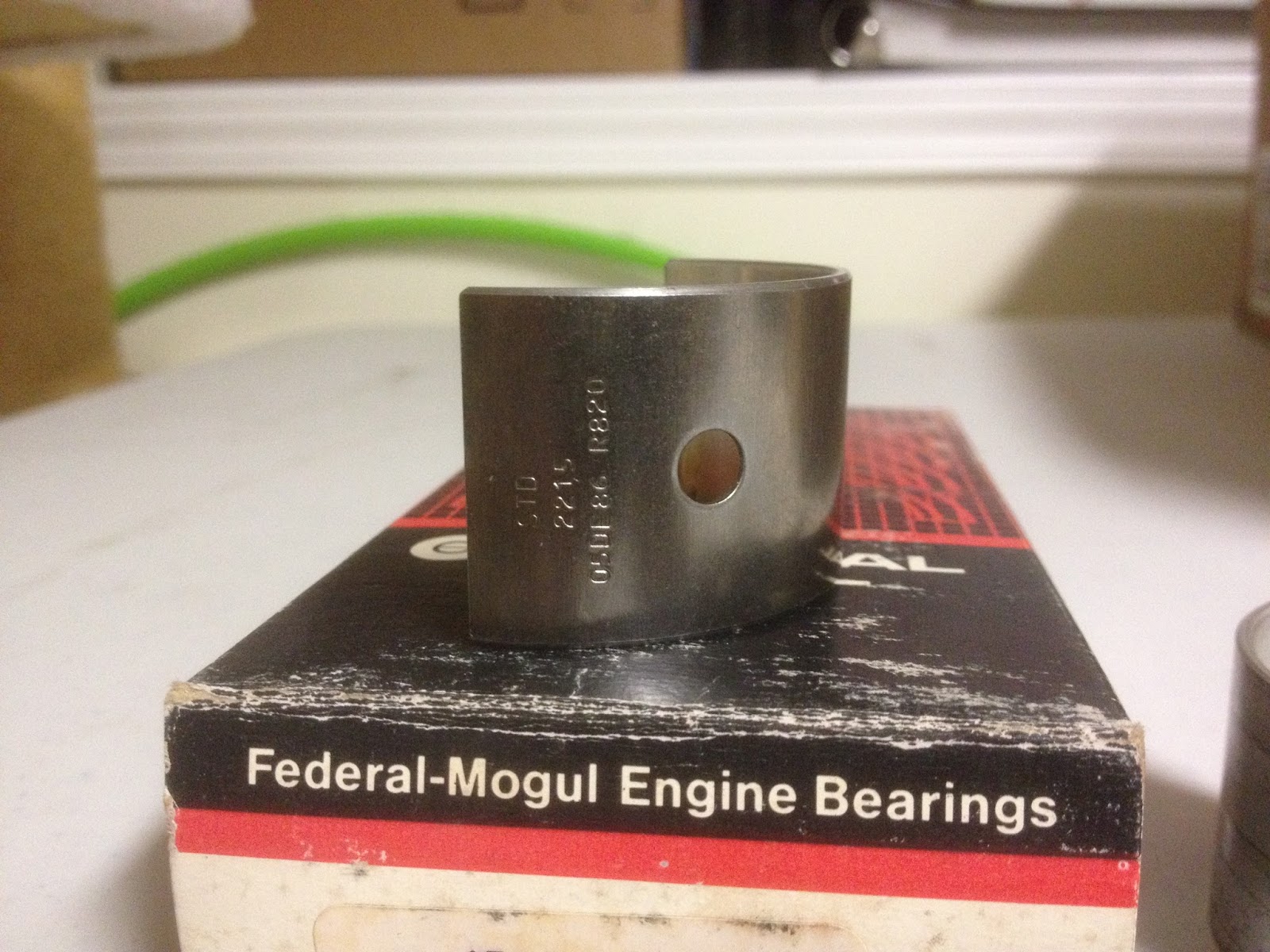
I began searching for clues as to what bearing replaced the usual #4 on this engine. First, I checked the bearing, and was able to find some numbers: 7D03 and 7D02, as well as STD (abbreviation of Standard, meaning this bearing fits new engine cases for the engine it's designed for, as opposed to bearings for engines that are line bored larger during overhaul.) So I started with that. Unfortunately, none of the parts stores I got in touch with were able to cross-reference that number to any of their bearing sets. Since the company that converted my engine for aircraft use is no longer in business, I couldn't contact them for help. I reached out to other folks who are part of the homebuilt and vw-for-aircraft community, but they were unable to provide any information. So I took some measurements and called the parts stores to see if they could match up a bearing set to dimensions. NONE of the parts stores I talked to had any way of doing that! At this point, I was at a loss. I looked into setting up the engine to run with the prop on the flywheel end instead of the pulley end, but my engine case was modified so I'd need a special bearing anyway, and without a way to order bearings by dimension, I was up a creek. Eventually, through several long nights exploring deep into the heart of the internet, I found a very large PDF from a company called King that links bearings to their vehicles AND THEIR DIMENSIONS, and was able to find fairly quickly with a search function *exactly* what I was after. (A direct link to the catalog is here: https://www.motorencenter.de/fileadmin/usercontent/King-Engine-Bearings-catalog-2015_2016.pdf )

Once armed with a part number, I was able to cross reference that number and get a Federal Mogul number, which Rock Auto had available for about 15 bucks. Upon arrival, I checked all the dimensions, and I'm quite convinced that this is the bearing used in my engine. What does it fit? Why, a 1968 Nissan 520 Pickup, of course.

New bearing below, along with old one for comparison:


With that mystery solved, I'm cleaning my crankcase and crankshaft so I can have them tested for cracks. I don't expect to have that done this week, as I'm coming down with something nasty and don't feel like doing *anything.* Baby steps are still progress....

Saturday, January 7, 2017

Engine DISassembly (Part 4)

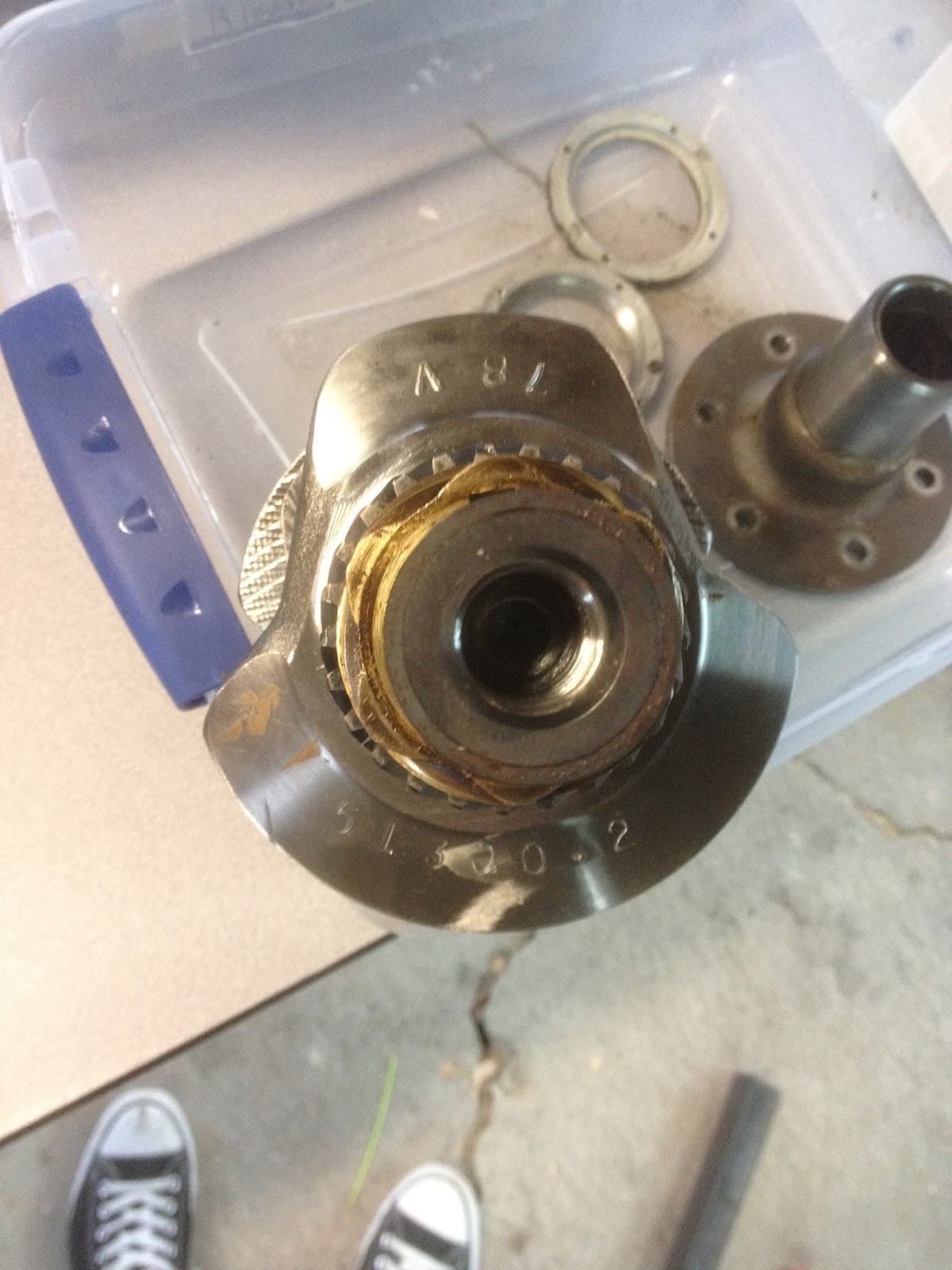
Between the holidays and lacking the proper tools half the time, it took me until now to finish gearing the engine apart. Mainly, the prop hub and crank gears were my main difficulties.  The prop hub I removed with the aid of a 3 jaw puller and two 4-foot extensions. One was a piece of angle iron drilled to fit the prop hub holes to keep the crankshaft from turning, the other was a 1" iron tube around a breaker bar.


Once the prop hub was off, the next task was removing the cam and distributor gears. I machined a couple of pieces of aluminum and made a makeshift puller for those. Forgot to take  a picture of that, but it worked. This picture shows the crank before the gears were removed.


The next two pictures are the main bearings, which I'm having difficulty locating replacements for. It seems the 4th bearing (bottom of first pic, right-most in second) is something different than normal, and I'm not sure where to look to find one that matches.


Once I have that figured out, I'll start ordering parts and cleaning things up for reassembly.


Sunday, November 20, 2016

Engine DISassembly (Part 3)

I've been stuck trying to find the right tools for the last week or so, and then trying to find the time, but I finally made some progress. The pictures below show a collar assembly on the front of the motor, behind the prop hub. Apparently this setup is an anomaly - no one I spoke with was able to identify it. There are 4 screws that hold the front collar onto the back collar, which has one screw into each side of the case. Once I got the right size hex key, these came off and the case came apart.


These two collars house an oil seal around the crank shaft where it exits the case. My first inclination is to replace the seal, but I'm not sure what kind of damage I might do removing the prop hub. I'll have to think about it.


Once the case was split, I pulled all the cam followers and labelled them so I could replace them in the same locations. I'll be taking a lot of pictures once I've cleaned things up, but the camshaft looks like it's in great shape, so that and the followers will probably stay.


The inside of the engine wasn't as pretty a machining job as I'd expected, but everything turned nice and smooth when it was all together, so I'm not too worried about it. I haven't found a reason for the fine metal shavings yet, which makes me uneasy. 


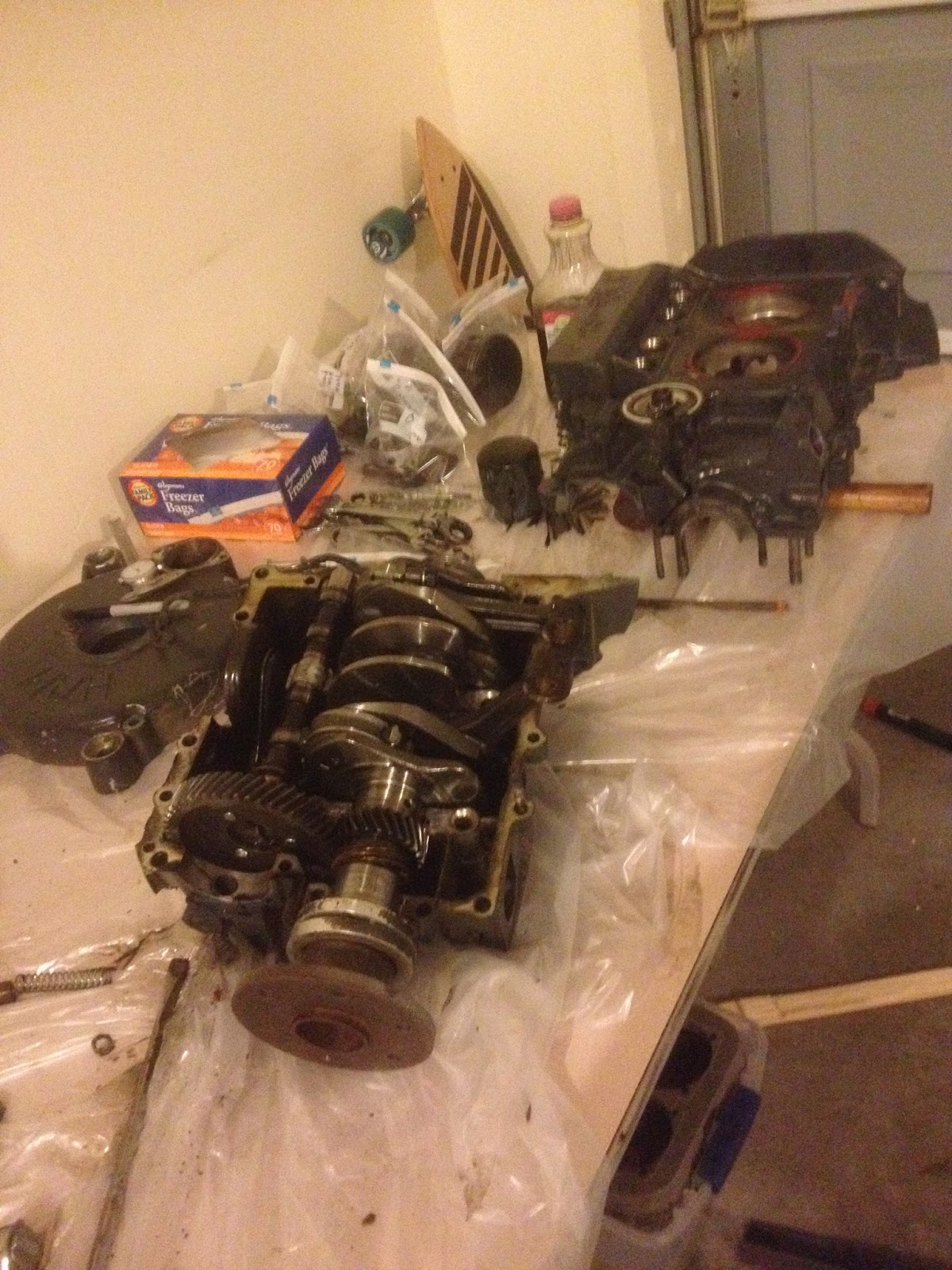
This is where I left it. There are only a couple of things left to do on the case before it can be cleaned up and inspected, and I don't expect the crankshaft assembly will be difficult to take apart. After that I can begin blueprinting, clean and inspect, order my parts, and put this thing back together.