Showing posts with label kr-2. Show all posts

Sunday, October 7, 2018

More Wood!

Ok, so I got the necessary braces installed. I also set up the seat well enough to take some measurements with a laser level simulating the horizon from my height when seated, and used that to generate templates for the canopy. However, in the meantime, there were a few more pieces of woodworking to attend to. The first is that, because of the way the fuselage is built, the plywood that stretches over the crossmembers behind the seat doesn't have a good way to glue to the longhorns.


The solution the previous builder used was to glue on more spruce to build the sides up to level, and it makes sense to me. So I went ahead and did the same. First I shaped some pieces of wood to follow the contours of the plane:


Then I glued them on, came back a day later, and started planing. I had to build up the center crossmember as well, because of the compound "dip" in the fuselage (Only needed about .02" or so, but it was easier to glue on a much thicker piece and plane it down later.) I used a hand plane held at an angle, so that the center x-member was being cut while the plane used the forward and rear x-members to set the height. Once the x-members were all co-planar, I planed the sides to match.


I didn't get a picture of the finished product, apparently. I was about ready to glue the plywood on, when I realized I'd want all of the gussets in place first; they'd be hard to add later! So I spent some time sanding tiny wood blocks to the right compound angles. It's not very difficult, but it was a little time consuming. I ended up needing 12; I was able to finish and glue 9 before I ran out of time.


The next time I was down, I finished making the gussets I needed and glued them overnight.


After everything had time to set, I planed and sanded everything down and cut the plywood to fit. This is pretty thin stuff, and I've found that by using a utility knife to cut through it, I can usually avoid sanding it except to break the sharp edges.


After several passes with the knife, it usually only needs a touch with sandpaper to get the edges smooth, and as long as you marked it right, it's bound to fit. All that was left was to glue it all together and clamp it down.


Next time I'm down, I'll pull the clamps off and start re-working the fiberglass seat backs. They need to be trimmed a little bit in order to fit the new angle. I'll probably cut the holes for the control sticks too, which will allow me to install those again and start fiddling with their location. I'm gearing up for all of the non-fiberglass things, since winter is almost upon us here. I've been working on designing a prop in CAD, as well as a control stick grip. Unfortunately, it looks like the canopy/aft deck/front deck is going to have to wait another winter... at least I have a plan for that now.

Monday, April 10, 2017

Starting to prep for assembly.... sort of.

With my crankshaft back and polished, I was able to begin reassembling the gears onto the nose.  First the key:


Heat up the cam drive gear, and slip it on:


Next the spacer and the new brass distributor gear.


I'm working out the best way to attach the prop hub - I know what orientation, but if I want it repeatable to exactly the same spot, I'll need to build some kind of jig that locates off of the cam drive gear. I'm not sure how much that will matter at this point.

In the meantime, I finished walnut blasting the case, and decided to try it on the heads as well. They were somewhat improved, but I'll still try soaking them in carb cleaner to try and get rid of more of the carbon that's built up. Ignore the ape blocking part of the picture...


And below, a chamber in progress to show my future self that it was, in fact, having an effect:


Once everything was sufficiently blasted, I used Simple Green to clean the case as best I could. I'll admit, I focused a little more on the outside than the inside, but I think it's pretty clean all the way through.


Once clean and dry, I cleaned the outside with solvent and got ready to paint. Bob Hoover says three things about painting the case: Do it, do it black, and do it thin. When I got the case, it was painted a dark gray... over top of a dark blue. Two layers of paint, the outer one fairly thick, were definitely not going to help much with thermal transfer, and yet it still flew that way. In light of that fact, I took Bob Hoover's advice on two of the points: I painted it, and I painted it thin.... and I painted it red.


I figure the color is less important than the paint thickness, so I cut the paint with Naptha and brushed it on, making sure to run the brush over any areas that looked like they had extra paint. The end result is definitely brush-textured, and not exactly what I had envisioned, but it looks pretty nifty all the same... and more importantly, it's protected from corrosion and it's not likely to overheat from the paint. I'll put this in the oven like I did the cylinders to get the paint nice and hard... it makes a big difference!

Thursday, February 23, 2017

Slow progress, but promising results!

A few months ago, my wife and I relocated to Rochester, NY for work, and to be closer to her family.
A small part of my new job is machining odd parts on a Tormach 1100, a 2.5 axis CNC mill. As a result, I'm now able to make *much* nicer and more complex parts than I could on my drill press in my shop back in PA. Which is really handy, since I ruined a couple of custom pieces taking this engine apart.


This is a two-piece housing that holds an oil seal. All of the information I could gather said that this should be attached in a way that prying and application of heat would allow its removal. All of that information was incorrect, as it turns out. Several #6 screws, hidden by RTV sealant and covered with paint, held this assembly on. I managed to bend it during my first failed attempt at removal, but even worse, I scraped the sealing face pretty bad with the screwdriver I was using to pry it off. As a result, I needed to replace both pieces.... and it just so happens I now have the tools to do so.

I didn't take a lot of pictures, but here's a shot of an aluminum blank next to one of the (almost) finished pieces:


I think the originals were turned on a lathe, based on the finish on the old parts vs the finish on the new parts. (Admittedly, I am not what most would call a competent machinist, so maybe I just failed to produce a quality part.) However, I think the new pieces will work out just fine.


According to the book I'm reading, "How to Rebuild your Volkswagen Aircooled Engine," Tom Wilson says the best way to clean the aluminum/magnesium engine case is with regular old soap.... with phosphate. Probably wasn't hard to come by when the book was written, but now it seems nobody sells it. I'm going to try regular old soap without phosphate, and see what happens. I'll be taking my crankshaft in next week to have it magnafluxed, and if it passes I'll be placing my big order for engine parts. My hope is that the engine will go back together pretty quickly, since there was no apparent damage and it ran ok before. 

As explanation for my apparent lack of significant progress, allow me to placate you with a picture of my son, who was born a few weeks ago, and has been eating up all of my time. Strangely, I don't mind....


Saturday, January 21, 2017

Those bearings fit a what!?

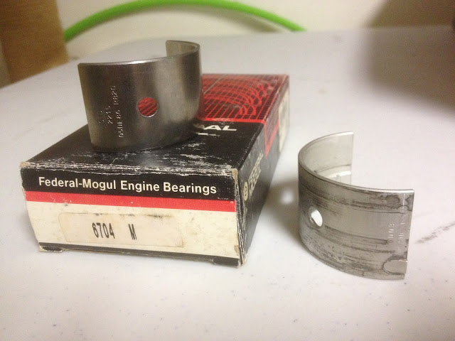
I began searching for clues as to what bearing replaced the usual #4 on this engine. First, I checked the bearing, and was able to find some numbers: 7D03 and 7D02, as well as STD (abbreviation of Standard, meaning this bearing fits new engine cases for the engine it's designed for, as opposed to bearings for engines that are line bored larger during overhaul.) So I started with that. Unfortunately, none of the parts stores I got in touch with were able to cross-reference that number to any of their bearing sets. Since the company that converted my engine for aircraft use is no longer in business, I couldn't contact them for help. I reached out to other folks who are part of the homebuilt and vw-for-aircraft community, but they were unable to provide any information. So I took some measurements and called the parts stores to see if they could match up a bearing set to dimensions. NONE of the parts stores I talked to had any way of doing that! At this point, I was at a loss. I looked into setting up the engine to run with the prop on the flywheel end instead of the pulley end, but my engine case was modified so I'd need a special bearing anyway, and without a way to order bearings by dimension, I was up a creek. Eventually, through several long nights exploring deep into the heart of the internet, I found a very large PDF from a company called King that links bearings to their vehicles AND THEIR DIMENSIONS, and was able to find fairly quickly with a search function *exactly* what I was after. (A direct link to the catalog is here: https://www.motorencenter.de/fileadmin/usercontent/King-Engine-Bearings-catalog-2015_2016.pdf )

Once armed with a part number, I was able to cross reference that number and get a Federal Mogul number, which Rock Auto had available for about 15 bucks. Upon arrival, I checked all the dimensions, and I'm quite convinced that this is the bearing used in my engine. What does it fit? Why, a 1968 Nissan 520 Pickup, of course.

New bearing below, along with old one for comparison:


With that mystery solved, I'm cleaning my crankcase and crankshaft so I can have them tested for cracks. I don't expect to have that done this week, as I'm coming down with something nasty and don't feel like doing *anything.* Baby steps are still progress....

Sunday, August 14, 2016

Outer Wings (Part 3)

On the left wing, I tried to modify the plans method to make it easier on myself. I cut out foam nose ribs that, rather than stick all the way out to the leading edge, only stuck out far enough to support the foam planks. Unfortunately, they weren't quite right, and it caused a lot of headache and frustration trying to rip out and replace foam. So this time, I did it a little closer to the plans method. Glued foam nose ribs in place, but then sanded them to the airfoil contour before adding the rest of the foam. It worked quite well, and was much easier than trying to work out the geometry of the nose supports changing size, length from the spar, and angle changes for washout.


Foam planks being cut and placed:


Once in place, I began the arduous sanding process yet again.


Honestly, it only took a couple hours, including frequent hydration (read: lost motivation) breaks and several "Is there *any* other way that would be *slightly* better?" pauses. One of those gave me the idea to cut slits along the entire length of my aluminum angle sanding block, and use that edge as a saw. It worked fairly well for large chunk removal, as long as you were careful not to cut too close to the final shape.


Eventually, I did manage to finish sanding the top of the wing (although not perfect - thank goodness for micro!) and got ready for another round of glassing. It's been so hot, I've been getting all of my supplies ready and all of the prep work done in the evening so I can get up early and finish glassing before 9 or 10 AM. Any later and the vinylester just sets up too fast. One interesting thing with vinylester that seems different than any other two-part system I've used - if the vinylester is gelling, and I'm not quite ready for it to set, I can actually add a little extra time by adding a little more vinylester (with hardener added, of course.) Not sure how or why, but it's saved me from a lot of repair work a couple of times.

I didn't get any pictures of the process, but it went like this:
Step one: micro from the front spar back to the trailing edge (skipping the spars)
Step two: lay one layer of 5.8 oz cloth and one layer of 1.5 oz cloth on the micro'd area, wet out completely
Step three: micro from the front spar forward and underneath, two inches past the chord line
Step four: wet out two layers of 5.8 oz cloth on a piece of 2 mil plastic, then lay the cloth in place on the leading edge of the wing. Much, much easier to do one layer at a time, otherwise you risk wrinkles in the bottom layer that are pretty impossible to get out once the resin begins to set.

The result is quite good, with very very few bubbles and only one small wrinkle. If the thunderstorms stay away long enough tomorrow,  I'll pull the plane out of the garage and flip it, then begin gluing foam around the bottom leading and trailing edges. Beginning to get excited about my progress, and I think I've figured out how I'll do my wing tips next.
Continued in Outer Wings (Part 4)

Outer Wings (Part 2)

Continued from Outer Wings (Part 1)
It's been a month, and I've been making progress. I had some foul-ups, which required tearing foam out and replacing it, but nothing too major. The following pictures show me finishing the main portion of the left wing.

Adding micro and foam to raise a low spot:


Glassing the top:


Flip the plane and repeat. Notice the two holes in the bottom - these were cut to address some slight leaking issues with the fuel tank.


I used a hand plane to shave a little bit of the spars off, so they were at or below the airfoil contour. You can see the wires poking out that I ran for wingtip lighting.


Originally I planned to build a tricycle gear, but decided to go with tailwheel instead. As a result, I needed to change the location of my sump drain on this wing. The original drain will remain plugged rather than torn out and re-glassed, because its proximity to the tank wall makes me unsure I could do so without causing more leaks.


One down, one to go. I learned a few things this time that will make the second wing easier... I hope.

Wednesday, March 2, 2016

Instrument Panel

I've been waiting for various hardware and tubing, but I haven't been twiddling my thumbs. I'm slowly acquiring the instruments for my plane, and I realized that having a plan in place would make picking up the right instruments a whole lot easier. I spent a few evenings trying to come up with panel arrangements using a photo editor, but I just couldn't get a feel for how it'd look in real life. So I had my local print shop print out a full-scale template of my instrument panel, overlaid with a ¼" grid. I then printed out full-sized instruments, as well as two glass screens I intend to incorporate. I cut all of this out, then used contact paper to make them more wear-resistant. What I ended up with was a completely customizable panel that shows me exactly how large everything will be in the plane. For some reason, this is a lot easier for the spatial reasoning part of my brain to work with. Here's a picture I took, not of a well thought-out layout, but just a quick proof of concept. (It's super blurry because of crummy lighting; the graphics are actually quite crisp. :D)

Tuesday, February 23, 2016

Control Sticks (Part 6)

Continued from Control Sticks (Part 5)
I finished cutting, shaping, and drilling the aluminum brackets, as well as the nylon bearing surfaces. I was very careful to make sure there would be no slop in the system when I was drilling the holes. Somehow, once again, I managed to order the wrong size hardware, so everything is temporarily assembled with other bolts I had on hand. I'm going to write up a list, or maybe a spreadsheet, that lays out what length bolt is ideal for various depths of material, because I can't seem to get it right. I test assembled everything on my workbench, and marked my layout so I could transfer the brackets to the plane.


Next I marked on the front spar where I wanted the brackets to be, lined them up and clamped them, and started drilling holes. I drilled one hole at a time, making sure everything lined up before committing to another hole. I really didn't wanna screw this up!

Everything in place, at least temporarily:


As you can see, I left the actual sticks long because I wasn't sure what length I'd want. I'm going to have to give them both a slight bend so they'll have enough throw to clear the front spar, whilst remaining far enough forward to be comfortable. I'll have to disassemble when the correct hardware arrives, and I may paint everything for corrosion resistance. I also need to redo the cables - only one of the three cables has a turnbuckle, which means if the cables ever stretched or needed adjustment, you'd have a heck of a time getting things realigned. Regardless, I'm much happier with this setup - lower profile, much better geometry, and working on this gave me an idea for a really simplistic aileron trim that'd be pretty easy to implement.


Monday, February 22, 2016

Control Sticks (Part 5)

Continued from Control Sticks (Part 4)
I got my brackets and sticks back from the welder today. I forgot to take a picture of the bracket, but this is how I fitted and attached the aluminum "fingers" to the sticks for welding.

I cut a square wooden peg to match the OD of the aluminum tube, drilled a hole where the aileron cable connection will be, then chucked it up in my lathe and turned the other end down to the ID. I turned far enough along the peg to set the depth of my jig.


This is the jig inserted into the tube, with the fingers already welded on. A small C-clamp held the fingers to the tube for tack welding, and then was removed for the full passes.


I realized after I got these sticks back that I had forgotten to mark where I needed the other set of holes. The main problem I faced was getting the holes in the center of the tubing and lined up with the existing holes. My drill press vise is just far enough off of level and plumb that I didn't trust it, so instead I used a speed square to find the center on both sides, then drill and ream the holes.


I drilled and tapped a length of ¼" 4130 tubing to connect my two control sticks along the horizontal axis, which turned out to be a little bit of a trick. I chucked the tubing in my lathe in order to drill it out so I could tap it, then locked the lathe up and tapped it by hand. I didn't drill quite far enough on one end, so I broke the tap... luckily, enough was sticking out that I could grab it with pliers and screw it right back out. Another trip to the hardware store for a new tap, and I was finished. I threaded in two AN42B "eye bolts," and it was ready to connect.


The last of the metalwork for the control sticks was to make the mounting brackets. I needed a set of brackets to hold the control sticks, and a set of brackets that will mount to the back of the rear spar where the pushrod will transition to cables. I did some adjusting to Mark Langford's drawings for the former, and did some math and drew up the latter on some graph paper. Here they are, attached to ⅛" 6061 T6 aluminum angles, but not cut out yet. I started by drilling all the holes, since that can be a difficult procedure once everything is cut out.


Tomorrow I hope to finish the mounting brackets and begin assembly in the fuselage.
Continued in Control Sticks (Part 6)

Thursday, February 18, 2016

Control Sticks (Part 4)

Continued from Control Sticks (Part 3)
I made progress on a lot of little things today. I laid out, drilled, and cut the nylon bearing surfaces for the control sticks. Forgot to take pictures of that. I redesigned the brackets that'll bolt to the front spar, because the plans I'm using account for a flap design I'm not using. I'm still waiting on the material I need to fashion the brackets, so I couldn't work any further on that. I also drew up plans for the bracket assembly to hold the bellcrank behind the rear spar,  where my pushrod will transition to cables for elevator control.


I've found no matter how much I work with various CAD software, the easiest and fastest way for me to design things is still on paper. (Partly because I usually spend about an hour fighting with my printer when I want the finished design printed to scale.)

I'm not a very proficient welder, and I don't have the right tools, so I sent my jigged-up assemblies out to be welded. Once those come back and the rest of my material shows up, I'll be able to finish this project and move forward. I believe I'll finish the rudder pedal assembly next. Sometimes I feel like I'm going to run out of work that isn't fiberglassing before it warms up, but I'm well known for taking *way* longer than I say I will to finish projects.