Showing posts with label kr2. Show all posts

Sunday, October 7, 2018

More Wood!

Ok, so I got the necessary braces installed. I also set up the seat well enough to take some measurements with a laser level simulating the horizon from my height when seated, and used that to generate templates for the canopy. However, in the meantime, there were a few more pieces of woodworking to attend to. The first is that, because of the way the fuselage is built, the plywood that stretches over the crossmembers behind the seat doesn't have a good way to glue to the longhorns.


The solution the previous builder used was to glue on more spruce to build the sides up to level, and it makes sense to me. So I went ahead and did the same. First I shaped some pieces of wood to follow the contours of the plane:


Then I glued them on, came back a day later, and started planing. I had to build up the center crossmember as well, because of the compound "dip" in the fuselage (Only needed about .02" or so, but it was easier to glue on a much thicker piece and plane it down later.) I used a hand plane held at an angle, so that the center x-member was being cut while the plane used the forward and rear x-members to set the height. Once the x-members were all co-planar, I planed the sides to match.


I didn't get a picture of the finished product, apparently. I was about ready to glue the plywood on, when I realized I'd want all of the gussets in place first; they'd be hard to add later! So I spent some time sanding tiny wood blocks to the right compound angles. It's not very difficult, but it was a little time consuming. I ended up needing 12; I was able to finish and glue 9 before I ran out of time.


The next time I was down, I finished making the gussets I needed and glued them overnight.


After everything had time to set, I planed and sanded everything down and cut the plywood to fit. This is pretty thin stuff, and I've found that by using a utility knife to cut through it, I can usually avoid sanding it except to break the sharp edges.


After several passes with the knife, it usually only needs a touch with sandpaper to get the edges smooth, and as long as you marked it right, it's bound to fit. All that was left was to glue it all together and clamp it down.


Next time I'm down, I'll pull the clamps off and start re-working the fiberglass seat backs. They need to be trimmed a little bit in order to fit the new angle. I'll probably cut the holes for the control sticks too, which will allow me to install those again and start fiddling with their location. I'm gearing up for all of the non-fiberglass things, since winter is almost upon us here. I've been working on designing a prop in CAD, as well as a control stick grip. Unfortunately, it looks like the canopy/aft deck/front deck is going to have to wait another winter... at least I have a plan for that now.

Wednesday, October 18, 2017

Crank Buildup... Again.


So, when I said earlier that the case was "torqued to spec" and that the crankshaft "didn't bind...." Turns out I lied. I didn't have two nuts on... and it turns out that those two little nuts caused a big problem.  Once I had *all* of the hardware on and torqued, the crankshaft stuck... pretty bad! I ended up doing a lot of digging, and it turns out that the piece that used to be the prop hub, which still provides a bearing surface, was the problem.

I started by trying different clocking orientations - pulling the hub, heating it up, rotating it slightly, and putting it back on - and I did find one position that was very close to perfect. However, it still had a sticking spot, and when I put a dial indicator on it, I could see why - while the hub was only out of concentric by about .0003, there was a single spot, like a lobe, that was more than a thousandth of an inch high. Now, I have a lathe, but I'm not confident enough in my abilities to do serious engine work. Nevertheless, I'm not willing to pay a machine shop another hundred to polish a single bearing surface into spec. 

So I chucked the crank into the lathe and set up to knock the lobe down with some emery cloth held in my tool holder, so I could just hit the high spot.


Once I thought I'd gotten close, I used some medium and then fine emery cloth to get all of the tooling marks off. Then I pulled the whole thing off the lathe and assembled and torqued the engine to spec again.


..........??????!!!!!!!!!!!!!!!!!!!!!!!

Rotates freely. Smooth as can be. I was pretty excited! It's still got contact across the whole bearing, too, so I didn't just turn it down so far it doesn't touch anything. (To give you an idea, I think I took about half a thou off of the bearing before I started with the emery cloth... so really, very long process for a very small amount of material.)

I cleaned the crankshaft up, re-lubed the connecting rods, and started to assemble them. Unfortunately, I can't find my LocTite to save my life. I think I left it in PA when I used it on my landing gear.


Yes, the connecting rods are pointing in wrong directions - that's just so the nuts are easy to get to. I couldn't just leave it all like that, so I went ahead and worked on setting up the distributor assembly. Because of the type of distributor I have, I don't think the orientation of the distributor drive shaft matters in the least. However, just in case I'm wrong, I oriented everything the way the book says to, marked it with red dykem, and put a holding screw in place to keep the distributor aligned correctly. I've gotta get a couple of new screws for that, though... these two are looking pretty buggered up.


I intend to assemble the crankshaft, then install it and the camshaft into the case, along with the correct end play shims on the flywheel, torque the case to spec and check free rotation one more time before the final assembly. If it all checks out, then I'll install the lifters, cam plug, and whatever else I'm forgetting, then put sealant on the case and bolt it all up for good. There's still a lot left to do, but this feels like a big turning point in this whole process.

Monday, October 16, 2017

Landing Gear (part 2)

(Continued from Landing Gear - Part One)

My landing gear legs finally showed up, so I took advantage of the last of the warm weather to get some fiberglassing done. I was pretty excited, since the plane has been sitting on jack stands for quite some time now, and I'm always nervous about it falling off when I'm getting in and out to make airplane noises.

Once I had the gear planed to thickness and edges chamfered, (ScotchPly is really hard on planer blades!) I wrapped a couple of layers of bi-directional cloth infused with epoxy around them, as per the instructions. After that cured, I hot-glued a couple of straws to the backs as a housing for the brake lines.


I mixed up some really thick micro and filled in all around the straws to help the next layers of fiberglass lay smoother.


Once that cured, I sanded it all smooth and wrapped the next layers of fiberglass cloth and epoxy around the back. Nothing to it, really.


The next step was to use some more micro and just squeegee it over the sides of the leg, so I could sand them nice and smooth (without adding much extra weight.) I also used a high-speed rotary tool to open up holes to the straws and sanded everything smooth.

Before I got to the fiberglassing stage, I had gotten the brackets all drilled and prepped. Because of the shape of the brackets, I had to get a little creative with the hole placement for the axles.


The next step was a little scary - the geometry of the axles and landing gear is sort of important, and I only got one shot at drilling holes into the fiberglass legs. I took my time and re-verified a couple times, and I still ended up with one axle not quite pointing the right direction - but I can machine a nice aluminum shim to fix it, since it's off by only a couple degrees. 

Once my holes were all drilled, I mixed up some flox, spread it on the brackets, and bolted the legs to the brackets for good.


While I waited for that to cure, I got my new rims and tires out, packed the bearings with grease, assembled them onto the axles, and the axles onto the brackets. It's starting to look serious now!


As soon as the epoxy showed the slightest indication of curing, I couldn't help but drag the whole assembly out to the garage and bolt it onto the plane. It's not a great picture, and there's a ton of crap in and around the plane, but it still looks a heck of a lot better with landing gear than it did on jack stands!


I haven't been idle with the engine - just frustrated, and lots of work for very slow progress. It was really good to get this out of the way, just to feel like i'm getting *something* done.

Sunday, August 27, 2017

Fit so nice, I made it twice....

Actually, it was the wrong material, so I kicked myself a few times and bought a new flywheel. This time, a *forged* flywheel, not a *cast* flywheel. Had I the sense to do more research ahead of time, I'd have only made it once. Nonetheless, the new version is around 300% *less* likely to break apart during flight.

That's version 2. Same dimensions, but machines a lot more like 4130 than the first one.


In this blurry picture I'm pointing out the locating step for the flexplate. That way I know it's concentric. I did the same on the inside for the prop extension:


Now that this is finished, I was able to start test assembling the crankcase. First, the connecting rods on the crankshaft:


Drop the crank assembly into the case and add some nuts, torqued to spec:


It still rotated freely after it was torqued, so that was a good sign. No rubbing or clearance issues so far. The next step was to add the head studs and check the piston deck height. I painted my head studs to help avoid corrosion:


And then I added them to the pile.


I added a cylinder and piston, and started taking measurements. I used a .030" shim under the cylinder, which is how the engine came to me. I set up my dial indicator and rotated the crank to TDC for that cylinder.


Zero'd up the dial indicator (though the photo makes it look off);


Using a piece of steel rod I had laying around as a straightedge, I measure deck clearance + rod width at 0.428" or so.


The rod I used measured 0.314", which means my clearance distance is 0.114". That's a lot more than I want! VW specs are between 0.040" and 0.080". I went back and checked, and the old pistons are the same as the new ones, and the old cylinders were within a couple thousandths of the new ones. That means that this engine was assembled wildly out of spec.... which shouldn't be a surprise, but it was. And means more work; removing the shims brings me down to 0.084", which is out of spec (and 0.024" more than I really want.) That means I'll have to chuck each cylinder up on the lathe and turn it down to what I want. 

Unless...

...unless the heads are also anomalies, and have a much smaller chamber than normal heads, in which case the cylinders need to be extra long.... Bottom line, the new priority is get the heads reconditioned and blueprinted so I know what kind of setup I need.

There has been nothing straightforward about this engine. Armed with the knowledge I've gained from this process, I believe the next engine I assemble will be from brand new parts that I know the details on.

Monday, July 3, 2017

Dowels are hard, PlastiGauge is soft.

It took a lot of work, but I got all four dowel pins out without damaging the crank. The two I put in came out easily enough with some vise grips and a bit of twisting and pulling... the two that were in from before were another story entirely. Nothing would touch them, including the hardened jaws of a *nice* set of vise grips. (Those are no longer a nice set of vise grips, by the way.) In the end, I discovered why machinists have drill bit sets up to half an inch with just a couple thou of difference all the way up...

...It's because hardened steel pins can't be drilled out with big steps between bit sizes! It took me a solid hour and a half to drill each pin out. However, both of them twisted out right before I broke through the wall of the pin (after a couple good taps with a hammer on the side of the pin to break it up a bit.)

I checked the face on a dial indicator, and at most it's out a single thousandth at the edge. That's about an inch from center, which means that might account for about 5 thousandths at the edge of the flywheel.... which means something else is amiss. I checked the flywheel by placing it on an indexer, supported by placing a tight tolerance block between the indexer and the mating face on the flywheel. Spin the indexer, check for runout.... I forget what I got, but it was insignificant (which is why I forgot it. :D) I was pretty puzzled at that point. However, since the pins were out of the crank, I was able to rotate the flywheel on the crank. How does that help us? Well, before I pulled the dowels, I'd marked on the flywheel exactly *where* the runout was, as well as *how much.* When I put the flywheel back on after the pins were out, I lined it up pretty close to where it was originally... and got pretty much the same results. (I didn't use an indicator, as I was less interested in how much it was out as *where* it was out.... and it was wobbling pretty obviously.) Ok, repeatability, that's good. So I rotated the flywheel 180 degrees and tried again. If it was the flywheel, that should've made no difference; the marks on the flywheel still should have been correct. If it was the crank face that was out, then the marks on the flywheel should have been exactly (or close to) opposite what the flywheel was showing the second time around.

So what did I find? Well.... actually, it was about 70 degrees off from where it was originally. I didn't know what to make of that, until I started taking careful measurements of everything. What I found was that the flywheel had a bit of a radius where it mated with the crankshaft, and the crankshaft did not have that radius. I think what's happening is that there's a tiny bit of play between the *side walls* of the flywheel and the crankshaft, and the radius causes the face of the flywheel to be tighter than the crankshaft can fit into. Add the radius and a little bit of slop and, unless the radius on the flywheel and the edge on the crankshaft are perfectly uniform and smooth, odds are the flywheel just isn't seating fully and is staying at a bit of an angle. The fix is simple; just cut a matching radius (or, much easier, a slightly relieved chamfer) on the crankshaft. The side walls and dowel pins will still locate the flywheel, and the face where the two meet won't lose much area. I like that idea better than cutting a sharp corner into the flywheel. 

I should mention, the reason that this is an easy fix is because I recently picked up a Jet 9x20 metal lathe. Just as soon as I finish getting that set up in the basement, this will be a pretty straightforward job. I'll be spending my evenings this week cleaning it up and, as soon as my insert tooling shows up next week, I'll be making chips and breaking tools. Also touching up airplane engine parts. 

I also got my oil galley plugs straked in place so they can't rotate out. I found one of my case savers was loose, so I used some red LocTite, filed a notch in it, and straked that in place as well. 

The last thing I wanted to do today was check my connecting rod bearing clearance. If you've never heard of PlastiGauge, you're in good company; none of the auto parts stores I went to had ever heard of it either. I ended up at a local NAPA, a company I spent 6 years working as a counterman for, and gave the kid at the counter the part number I remembered as being correct. "Huh, it says we've got 12 in stock. What is it again?" It comes from the warehouse packaged as a dozen, so I guess it shouldn't surprise me he'd never heard of it; he'd never sold any of it. Anyways, PlastiGauge is a kind of plastic-y wax string that's very precisely formed. A strip of it is placed between two surfaces you want to check clearance on, and those two surfaces are brought together however they will be brought together during final assembly. In this case, those surfaces are the connecting rods with bearings installed, and the crankshaft. Blurry picture, but the green little stripe in the middle of the white grease is the PlastiGauge before the con rod is tightened....


...And after:


The lighting was pretty awful. However, I can tell you that the strip of green that's *not* a weird reflection is the one above the .0015" mark. Basically, that wax gets squished to different widths based on how much clearance is available, and the package the wax comes in has a gauge on the side to check it with. All four journals had *exactly* the same width as the .0015" mark, and they were all very even stripes from one side of the journal to the other. (If the journals or the con rods had any taper, that would've shown up as a tapered stripe.) The specs for this engine are 0.0008-0.0025, so I'm smack in the middle of where I want to be. Any wear is going to cause that clearance to open up, and I've got a solid thousandth of an inch for it to open up before I make it out of the range I want to be in.

I'll putz around with little things here and there, but mainly I'll be setting up that lathe and taking some test cuts to get to know it. I've got to do my touch up on the crankshaft, and a couple other things, and then I can start test assembling everything. 

Sunday, June 18, 2017

MORE Case and Crank prep...

It's been slow going lately, but progress seems to be taking place. I got lost in a lot of thought experiments and what-ifs, and (as is usually the case,) ended up right back where I started. So I cut the top off of the flywheel flange on the case, did a little bit of clearing on the inside of the case (some spots didn't seem to have more than a few thou of room for rotating parts), and used a Dremel to carve away a couple of channels for the engine mount in the back.


I also pulled all the aluminum plugs to get an idea of how much stuff was trapped in the case...


...And there was a lot! Much of that was from walnut blasting the case, but I found a good number of metal shavings as well. I'm glad I pulled the plugs... Next I tapped the holes for various pipe thread plugs, ranging from 1/16" NPT up to 3/8" NPT. I used a 1/2" NPT to tap a larger hole in the front for an oil temp sensor, because I've read bad things about the current temp sensor location (near the flywheel end of the case) actually reading quite a bit lower as a result of not being in a high-flow area. The new place is directly in the oil flow as it enters the oil pump, so it'd be hard to get a better reading than that!

Drilling and tapping the magnesium was quite easy, actually... in that the magnesium tapped without much force. There were a few places that I had to tap a few threads, then grind the tap down, then tap a few more, then grind, back and forth a few more times until the plug fit the way I wanted it to. There's one hole that I may have tapped just a little too hard and began to mess up the threads, but the plug threads in just fine and seems to have full contact along the entire length and circumference of the plug, so I'm going to leave it.

Now that all of the holes are prepped, I'll pull all the plugs out for another cleaning session. The last step will be to file a notch in each of the plugs so I can swage the case metal into those notches as a final insurance against the plugs working their way back out.


I forgot to take pictures, but I drilled the crankshaft for a couple more dowel pins. When I received it, it only had two, which was probably fine running the prop off the other end, but I'm not comfortable only using two running it with the prop hanging off the flywheel. So I drilled two more holes, reamed them, and tried to put the dowels in.... oops! One of the holes is *way* too loose! So I ordered a 11/32" drill bit blank, cut it down to the right length to be a dowel pin, and re-reamed the hole to be a press fit. This really isn't a bad plan anyway, as it keeps my flywheel aligned the same way every time it's reassembled, and the only extra work I'd have to do on a new flywheel is drill one hole slightly larger.

Upon reassembly of the flywheel and crank, I realized the flywheel is running about 60 thousandths out of true at the outermost edge. Not cool at all. So my next step is to remove the dowels and see if the crank face is out, but my bet is that somewhere along the way some burrs crept up and are keeping the crank from seating correctly. At least, I hope that's what happened... otherwise it's back to the machine shop.

Monday, April 10, 2017

Starting to prep for assembly.... sort of.

With my crankshaft back and polished, I was able to begin reassembling the gears onto the nose.  First the key:


Heat up the cam drive gear, and slip it on:


Next the spacer and the new brass distributor gear.


I'm working out the best way to attach the prop hub - I know what orientation, but if I want it repeatable to exactly the same spot, I'll need to build some kind of jig that locates off of the cam drive gear. I'm not sure how much that will matter at this point.

In the meantime, I finished walnut blasting the case, and decided to try it on the heads as well. They were somewhat improved, but I'll still try soaking them in carb cleaner to try and get rid of more of the carbon that's built up. Ignore the ape blocking part of the picture...


And below, a chamber in progress to show my future self that it was, in fact, having an effect:


Once everything was sufficiently blasted, I used Simple Green to clean the case as best I could. I'll admit, I focused a little more on the outside than the inside, but I think it's pretty clean all the way through.


Once clean and dry, I cleaned the outside with solvent and got ready to paint. Bob Hoover says three things about painting the case: Do it, do it black, and do it thin. When I got the case, it was painted a dark gray... over top of a dark blue. Two layers of paint, the outer one fairly thick, were definitely not going to help much with thermal transfer, and yet it still flew that way. In light of that fact, I took Bob Hoover's advice on two of the points: I painted it, and I painted it thin.... and I painted it red.


I figure the color is less important than the paint thickness, so I cut the paint with Naptha and brushed it on, making sure to run the brush over any areas that looked like they had extra paint. The end result is definitely brush-textured, and not exactly what I had envisioned, but it looks pretty nifty all the same... and more importantly, it's protected from corrosion and it's not likely to overheat from the paint. I'll put this in the oven like I did the cylinders to get the paint nice and hard... it makes a big difference!

Saturday, January 21, 2017

Those bearings fit a what!?

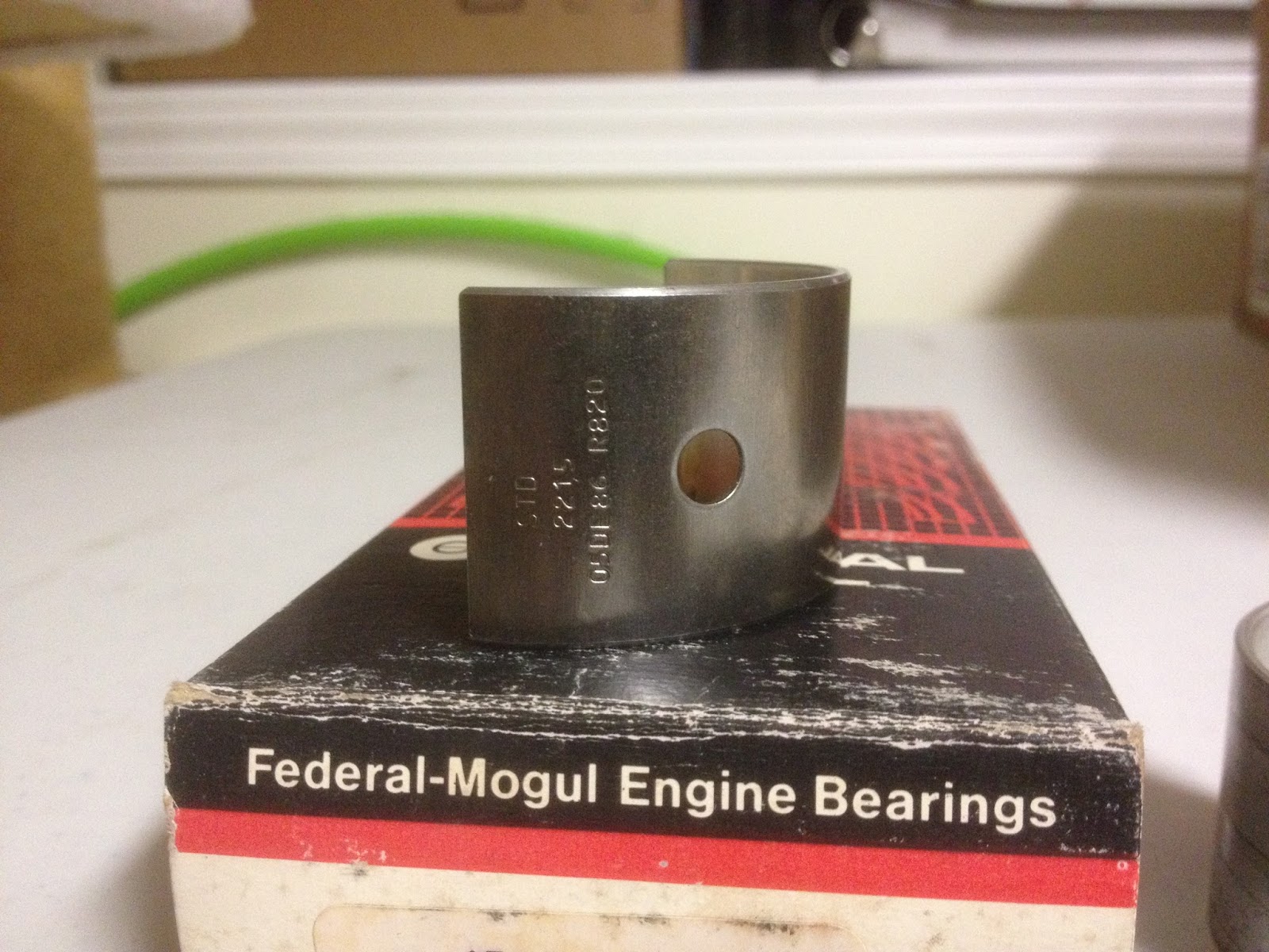
I began searching for clues as to what bearing replaced the usual #4 on this engine. First, I checked the bearing, and was able to find some numbers: 7D03 and 7D02, as well as STD (abbreviation of Standard, meaning this bearing fits new engine cases for the engine it's designed for, as opposed to bearings for engines that are line bored larger during overhaul.) So I started with that. Unfortunately, none of the parts stores I got in touch with were able to cross-reference that number to any of their bearing sets. Since the company that converted my engine for aircraft use is no longer in business, I couldn't contact them for help. I reached out to other folks who are part of the homebuilt and vw-for-aircraft community, but they were unable to provide any information. So I took some measurements and called the parts stores to see if they could match up a bearing set to dimensions. NONE of the parts stores I talked to had any way of doing that! At this point, I was at a loss. I looked into setting up the engine to run with the prop on the flywheel end instead of the pulley end, but my engine case was modified so I'd need a special bearing anyway, and without a way to order bearings by dimension, I was up a creek. Eventually, through several long nights exploring deep into the heart of the internet, I found a very large PDF from a company called King that links bearings to their vehicles AND THEIR DIMENSIONS, and was able to find fairly quickly with a search function *exactly* what I was after. (A direct link to the catalog is here: https://www.motorencenter.de/fileadmin/usercontent/King-Engine-Bearings-catalog-2015_2016.pdf )

Once armed with a part number, I was able to cross reference that number and get a Federal Mogul number, which Rock Auto had available for about 15 bucks. Upon arrival, I checked all the dimensions, and I'm quite convinced that this is the bearing used in my engine. What does it fit? Why, a 1968 Nissan 520 Pickup, of course.

New bearing below, along with old one for comparison:


With that mystery solved, I'm cleaning my crankcase and crankshaft so I can have them tested for cracks. I don't expect to have that done this week, as I'm coming down with something nasty and don't feel like doing *anything.* Baby steps are still progress....