Showing posts with label airplane. Show all posts

Sunday, October 7, 2018

More Wood!

Ok, so I got the necessary braces installed. I also set up the seat well enough to take some measurements with a laser level simulating the horizon from my height when seated, and used that to generate templates for the canopy. However, in the meantime, there were a few more pieces of woodworking to attend to. The first is that, because of the way the fuselage is built, the plywood that stretches over the crossmembers behind the seat doesn't have a good way to glue to the longhorns.


The solution the previous builder used was to glue on more spruce to build the sides up to level, and it makes sense to me. So I went ahead and did the same. First I shaped some pieces of wood to follow the contours of the plane:


Then I glued them on, came back a day later, and started planing. I had to build up the center crossmember as well, because of the compound "dip" in the fuselage (Only needed about .02" or so, but it was easier to glue on a much thicker piece and plane it down later.) I used a hand plane held at an angle, so that the center x-member was being cut while the plane used the forward and rear x-members to set the height. Once the x-members were all co-planar, I planed the sides to match.


I didn't get a picture of the finished product, apparently. I was about ready to glue the plywood on, when I realized I'd want all of the gussets in place first; they'd be hard to add later! So I spent some time sanding tiny wood blocks to the right compound angles. It's not very difficult, but it was a little time consuming. I ended up needing 12; I was able to finish and glue 9 before I ran out of time.


The next time I was down, I finished making the gussets I needed and glued them overnight.


After everything had time to set, I planed and sanded everything down and cut the plywood to fit. This is pretty thin stuff, and I've found that by using a utility knife to cut through it, I can usually avoid sanding it except to break the sharp edges.


After several passes with the knife, it usually only needs a touch with sandpaper to get the edges smooth, and as long as you marked it right, it's bound to fit. All that was left was to glue it all together and clamp it down.


Next time I'm down, I'll pull the clamps off and start re-working the fiberglass seat backs. They need to be trimmed a little bit in order to fit the new angle. I'll probably cut the holes for the control sticks too, which will allow me to install those again and start fiddling with their location. I'm gearing up for all of the non-fiberglass things, since winter is almost upon us here. I've been working on designing a prop in CAD, as well as a control stick grip. Unfortunately, it looks like the canopy/aft deck/front deck is going to have to wait another winter... at least I have a plan for that now.

Wednesday, October 18, 2017

Crank Buildup... Again.


So, when I said earlier that the case was "torqued to spec" and that the crankshaft "didn't bind...." Turns out I lied. I didn't have two nuts on... and it turns out that those two little nuts caused a big problem.  Once I had *all* of the hardware on and torqued, the crankshaft stuck... pretty bad! I ended up doing a lot of digging, and it turns out that the piece that used to be the prop hub, which still provides a bearing surface, was the problem.

I started by trying different clocking orientations - pulling the hub, heating it up, rotating it slightly, and putting it back on - and I did find one position that was very close to perfect. However, it still had a sticking spot, and when I put a dial indicator on it, I could see why - while the hub was only out of concentric by about .0003, there was a single spot, like a lobe, that was more than a thousandth of an inch high. Now, I have a lathe, but I'm not confident enough in my abilities to do serious engine work. Nevertheless, I'm not willing to pay a machine shop another hundred to polish a single bearing surface into spec. 

So I chucked the crank into the lathe and set up to knock the lobe down with some emery cloth held in my tool holder, so I could just hit the high spot.


Once I thought I'd gotten close, I used some medium and then fine emery cloth to get all of the tooling marks off. Then I pulled the whole thing off the lathe and assembled and torqued the engine to spec again.


..........??????!!!!!!!!!!!!!!!!!!!!!!!

Rotates freely. Smooth as can be. I was pretty excited! It's still got contact across the whole bearing, too, so I didn't just turn it down so far it doesn't touch anything. (To give you an idea, I think I took about half a thou off of the bearing before I started with the emery cloth... so really, very long process for a very small amount of material.)

I cleaned the crankshaft up, re-lubed the connecting rods, and started to assemble them. Unfortunately, I can't find my LocTite to save my life. I think I left it in PA when I used it on my landing gear.


Yes, the connecting rods are pointing in wrong directions - that's just so the nuts are easy to get to. I couldn't just leave it all like that, so I went ahead and worked on setting up the distributor assembly. Because of the type of distributor I have, I don't think the orientation of the distributor drive shaft matters in the least. However, just in case I'm wrong, I oriented everything the way the book says to, marked it with red dykem, and put a holding screw in place to keep the distributor aligned correctly. I've gotta get a couple of new screws for that, though... these two are looking pretty buggered up.


I intend to assemble the crankshaft, then install it and the camshaft into the case, along with the correct end play shims on the flywheel, torque the case to spec and check free rotation one more time before the final assembly. If it all checks out, then I'll install the lifters, cam plug, and whatever else I'm forgetting, then put sealant on the case and bolt it all up for good. There's still a lot left to do, but this feels like a big turning point in this whole process.

Thursday, February 23, 2017

Slow progress, but promising results!

A few months ago, my wife and I relocated to Rochester, NY for work, and to be closer to her family.
A small part of my new job is machining odd parts on a Tormach 1100, a 2.5 axis CNC mill. As a result, I'm now able to make *much* nicer and more complex parts than I could on my drill press in my shop back in PA. Which is really handy, since I ruined a couple of custom pieces taking this engine apart.


This is a two-piece housing that holds an oil seal. All of the information I could gather said that this should be attached in a way that prying and application of heat would allow its removal. All of that information was incorrect, as it turns out. Several #6 screws, hidden by RTV sealant and covered with paint, held this assembly on. I managed to bend it during my first failed attempt at removal, but even worse, I scraped the sealing face pretty bad with the screwdriver I was using to pry it off. As a result, I needed to replace both pieces.... and it just so happens I now have the tools to do so.

I didn't take a lot of pictures, but here's a shot of an aluminum blank next to one of the (almost) finished pieces:


I think the originals were turned on a lathe, based on the finish on the old parts vs the finish on the new parts. (Admittedly, I am not what most would call a competent machinist, so maybe I just failed to produce a quality part.) However, I think the new pieces will work out just fine.


According to the book I'm reading, "How to Rebuild your Volkswagen Aircooled Engine," Tom Wilson says the best way to clean the aluminum/magnesium engine case is with regular old soap.... with phosphate. Probably wasn't hard to come by when the book was written, but now it seems nobody sells it. I'm going to try regular old soap without phosphate, and see what happens. I'll be taking my crankshaft in next week to have it magnafluxed, and if it passes I'll be placing my big order for engine parts. My hope is that the engine will go back together pretty quickly, since there was no apparent damage and it ran ok before. 

As explanation for my apparent lack of significant progress, allow me to placate you with a picture of my son, who was born a few weeks ago, and has been eating up all of my time. Strangely, I don't mind....


Saturday, January 7, 2017

Engine DISassembly (Part 4)

Between the holidays and lacking the proper tools half the time, it took me until now to finish gearing the engine apart. Mainly, the prop hub and crank gears were my main difficulties.  The prop hub I removed with the aid of a 3 jaw puller and two 4-foot extensions. One was a piece of angle iron drilled to fit the prop hub holes to keep the crankshaft from turning, the other was a 1" iron tube around a breaker bar.


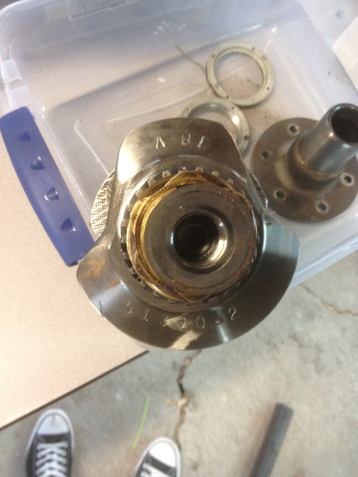
Once the prop hub was off, the next task was removing the cam and distributor gears. I machined a couple of pieces of aluminum and made a makeshift puller for those. Forgot to take  a picture of that, but it worked. This picture shows the crank before the gears were removed.


The next two pictures are the main bearings, which I'm having difficulty locating replacements for. It seems the 4th bearing (bottom of first pic, right-most in second) is something different than normal, and I'm not sure where to look to find one that matches.


Once I have that figured out, I'll start ordering parts and cleaning things up for reassembly.


Sunday, August 28, 2016

Wing Tips (Part 3)

After hot wire cutting, I did some sanding to smooth it out, as well as making a radius on the bottom edge. I also trimmed away 3/4" of the trailing edge foam and filled it with micro, same as with the wing. After I was happy with the shape, I put two layers of 5.8 oz cloth on the top, two layers on the bottom, and two layers wrapped around the thin edge. The top and bottom layers extend about 6 inches onto the existing wing, and the whole thing is quite stiff and strong. I don't think I'll make any changes to the process for the other side, so I won't bother uploading any new pictures unless something unexpected happens. Here's the (semi) finished product.


Thursday, August 25, 2016

Wing Tips (Part 2)

Once the foam was all glued up, I sanded it down to shape just like the rest of the wing. I ended up with 15" of extra length, and my final airfoil chord at 33.75 inches and right around 0* incidence. Time to make the actual tip.


I'm going to be using a modified Hoerner tip. I used a paper written by Hoerner, as well as the video I linked to in the previous post, to come up with my own hybrid. Hoerner describes and promotes a wingtip that is simply cut at about a 45* angle from bottom to top, which was my original plan. However, in the video uploaded by YouTuber schmleff, his tip changes angles as the wing thickness changes. I'll be using aspects of both, and hopefully not eliminating the good effects of both in the process.

Hoerner tip:


Schmleff tip: (before additional nose shaping)


My adaptation:


Hoerner tip pros: highest L/D ratio without using "tip devices" (i.e. winglets), as a result of vortices around the outside of the wing being pushed out past the wing.

Schmleff tip pros: Higher lift at tips, causing greater roll stability and lowering stall speed

My tips: (in theory?) push vortices past the wing, and give smooth airflow transition to rear of tip where greater lift can be achieved with minimal decrease in top speed, allowing a potentially lower stall speed and therefore slower landing speed.

Enough about theory, here's how it went.

I started by following the schmleff video, taping about 3/8" below the top of the airfoil and 6" inboard of the tip on the bottom of the airfoil. (Wing is upside down in picture.)


I went ahead and cut the foam with the hot wire cutter at this stage, giving me the start of the schmleff tip.


I had a fancy jig planned that would hold the hot wire cutter at the right angle as I moved it over the front of the wing, but I realized since I had this modeled in CAD already, I might as well just plot it on my wing, tape it off, and cut it. Could have done that all at once, but I didn't, so I had to glue back some of the foam I just cut off. The nice thing about hot wire cutting is the pieces fit back on really nice.


Once I had that all taped up, I used the hot wire cutter again, and the general shape was achieved.


I like the way that turned out. All that's left is about 10 minutes of touch-up sanding, and to round the leading edge a little bit, and then I'll be ready to glass it.

Monday, August 22, 2016

Wing Tips (Part 1)

With both wings glassed, it's time for wing tips. I'm doing a version of Hoerner tips, which ought to reduce drag and increase lift by moving the inherent turbulence out past the wing. I did a fair amount of research, and came up with a couple of studies that promoted the Hoerner tip, and a few studies that promoted simple round or rhombus end plates as much better options. I don't like the idea of those end plates, because 1. if they aren't lined up right they'll increase drag, and 2. I don't like how they look. I'm basically following a great Youtube video found here, which details the entire process.

The first step I needed to take was making my wing straight and square on the end. This should have been done by shaping the spars accordingly, but I wasn't smart enough to think about that at the time. As a result, the ends of my wings are pretty wavy.


In order to fix this, I started by cutting an oversized airfoil from a piece of 2" foam, and cut it into a bunch of sections that would follow the angles on the wing endplate.


These were glued on and left to cure. Once they were set, I sanded them to match the rest of the wing.
Next I laid a framing square along my front spar, which is perpendicular to the aircraft's centerline, and used that to draw a line on the top and bottom of the foam 1" outboard of the endplate. After the lines were drawn, I laid some 2" aluminum foil HVAC tape along the lines all the way around the foam.


Once that was lined up and pressed on really well, I fired up my hot wire foam cutter and used the tape as a template. When I was finished, I had a really nice straight, square, flat end plate to glue my wing tip onto.


I'll be extending my wing 15" outboard of the 3/32" plywood endplate, in order to try and squeeze a little better glide rate out of the plane. From what I've been reading, it doesn't seem to have much of a speed penalty, and a number of folks have extended their wing 18" or more this way without adding to the length of the spar. Since the foam I used to fix the wavy endplate issue is 1" outboard of the main spar, I'll add 14" of foam by cutting 7 pieces of 2" stuff and gluing it all together. It's cut to a slightly large airfoil shape to help me get it to the final shape faster. I'm using 3M spray adhesive so that my hot wire foam cutter will be able to slice through it once it's ready, although I'm slightly skeptical about how well that'll hold the foam for sanding.


Continued in Wing Tips (Part 2)

Friday, August 19, 2016

Outer Wings (Part 6)

Continued from Outer Wings (Part 5)
Today I finished sanding the wing to shape. My micro trailing edge is nice and solid, and I sanded the overlapping fiberglass on the leading edge down nice and smooth for the next couple of layers. I hand planed the spars down to slightly below the airfoil contour, which was much easier after I took five minutes and sharpened the blade. I didn't take many pictures, but I did document how I'm prepping the sump drain as well as the WAF cut-outs in the foam. The cut-outs each get some one-on-one time with a Dremel, so that the foam is slightly recessed. Next I take a piece of pre-layed-up fiberglass and cut it to fit the cut-out.


Once I've got all four cut to fit, I mix up some micro and apply it to the foam, then set the fiberglass in the cut-outs. I'm not too picky about how it lays, but generally I try to make it as close to the airfoil contour as possible, erring below rather than above.

For the sump drain, I start by attaching a circular piece of duct tape over the hole. Then I use a really thick micro to build up from the aluminum block to the airfoil contour. While the micro is in the "green" stage, I use a Forstner bit to generate a nice circular hole down to the aluminum block where the duct tape is, which gets removed (because it's now all gummy and may not keep the resin out during the big layup.)


I'll replace the duct tape before I do my layup. I'm prepping for that by cutting templates out of plastic 2 mil drop cloth, then cutting the fiberglass from that. If everything goes well, by this time tomorrow the wing will be finished and off the plane.