Showing posts with label hapi. Show all posts

Wednesday, August 15, 2018

Whoops... This is a new problem!

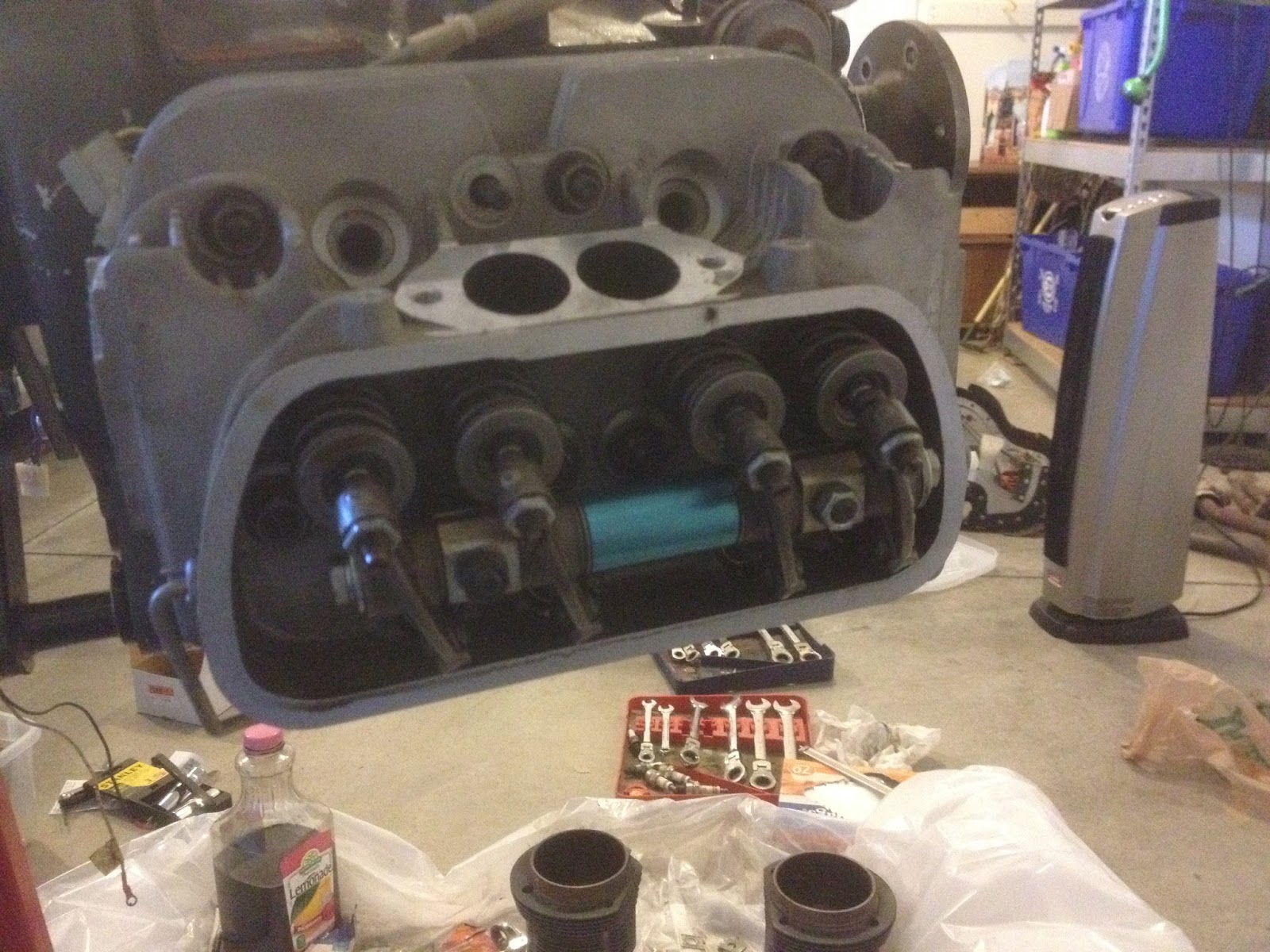
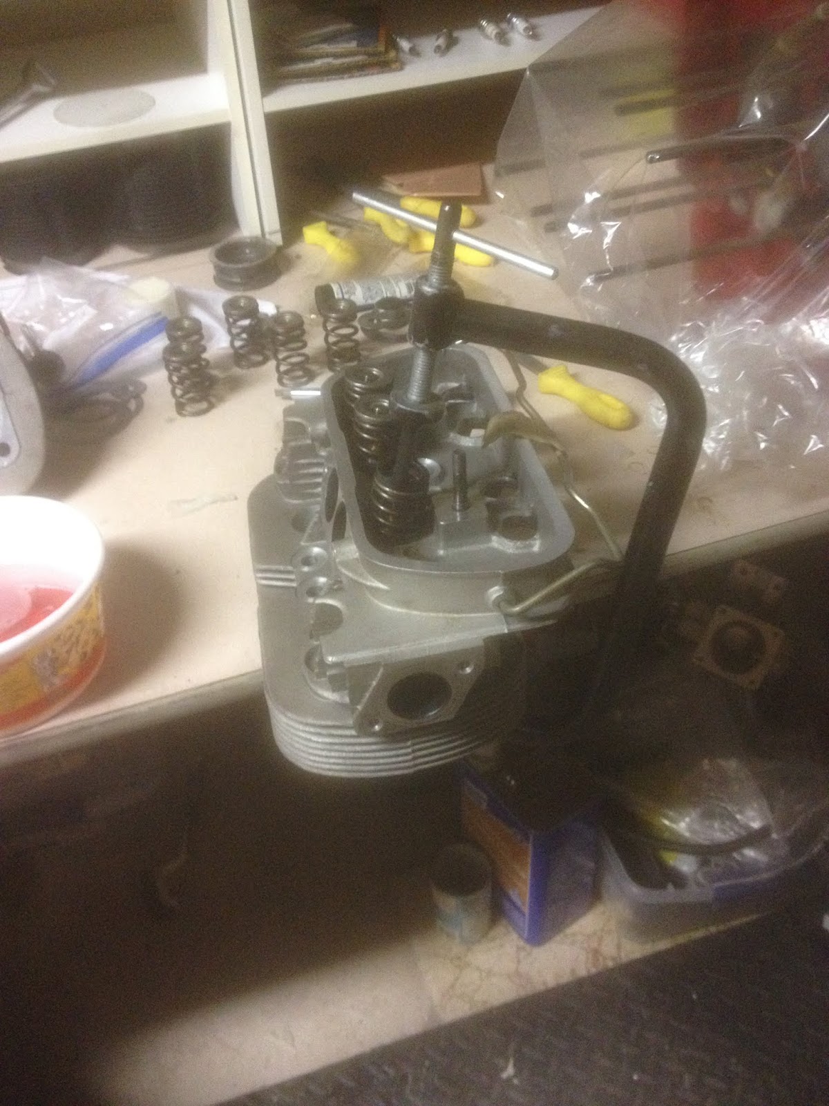
Ok, ok, it's not really a problem... at least, it's not a mistake or a roadblock or a money pit kind of problem. The last few weeks have been pretty good - I finished assembling my heads,


made a plate for bolting the cylinders on to check deck height for each piston/cylinder set,


(btw, this gave me wacky results - I had to remake the plate to cover *both* cylinders at once, the same way the head will when the engine is assembled)


(Again, not like this.) and then made a new two-cylinder capturing plate and measured deck height at final torque.

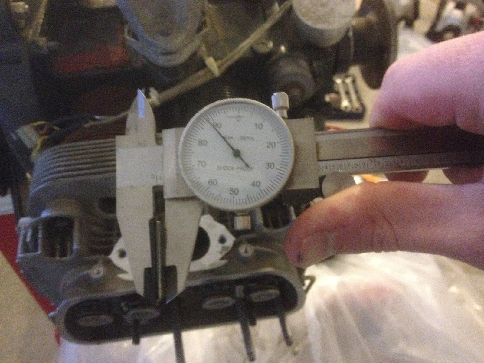
Deck heights were all pretty darn close - I had a spread of 0.1997", 0.122", 0.1225", 0.125". Because I have a lathe handy, I was planning on chucking up the pistons and dusting them all perfect - but after doing the math, I realized that by arranging the heads correctly, my compression ratio would range from 7.976:1 to 8.021:1. In other words, a maximum difference of 0.045:1......... I think that's close enough!

I went ahead and painted the cylinder numbers on the case according to convention, and then marked the cylinders and pistons accordingly.


Since I wanted the heads on certain sides, I went ahead and marked them as well.


The last thing I have to do on the engine for now is bag everything up - each head will get a bag, each piston/cylinder will get a bag, and the block will get a bag. I don't want to have to carry the assembled engine up out of the basement when we move in a few months, so I'll just leave it in pieces until it's in a shop that's on the ground floor. After that, I'll assemble it and bag it again, until I need to take more measurements off it or am ready to attach it to an airplane. So what's the problem, you ask? Well, this engine has been about the only thing I can do related to my plane right now. Every couple weeks we travel to see the rest of my family, and I can sneak away for a few hours to work on the plane when we're there, but otherwise it's just me and the engine. Now that I'm mostly done with that, I'm not sure how I'll keep making progress... and if I'm not making progress, I'll drive my wife over the edge. :)

Monday, July 3, 2017

Dowels are hard, PlastiGauge is soft.

It took a lot of work, but I got all four dowel pins out without damaging the crank. The two I put in came out easily enough with some vise grips and a bit of twisting and pulling... the two that were in from before were another story entirely. Nothing would touch them, including the hardened jaws of a *nice* set of vise grips. (Those are no longer a nice set of vise grips, by the way.) In the end, I discovered why machinists have drill bit sets up to half an inch with just a couple thou of difference all the way up...

...It's because hardened steel pins can't be drilled out with big steps between bit sizes! It took me a solid hour and a half to drill each pin out. However, both of them twisted out right before I broke through the wall of the pin (after a couple good taps with a hammer on the side of the pin to break it up a bit.)

I checked the face on a dial indicator, and at most it's out a single thousandth at the edge. That's about an inch from center, which means that might account for about 5 thousandths at the edge of the flywheel.... which means something else is amiss. I checked the flywheel by placing it on an indexer, supported by placing a tight tolerance block between the indexer and the mating face on the flywheel. Spin the indexer, check for runout.... I forget what I got, but it was insignificant (which is why I forgot it. :D) I was pretty puzzled at that point. However, since the pins were out of the crank, I was able to rotate the flywheel on the crank. How does that help us? Well, before I pulled the dowels, I'd marked on the flywheel exactly *where* the runout was, as well as *how much.* When I put the flywheel back on after the pins were out, I lined it up pretty close to where it was originally... and got pretty much the same results. (I didn't use an indicator, as I was less interested in how much it was out as *where* it was out.... and it was wobbling pretty obviously.) Ok, repeatability, that's good. So I rotated the flywheel 180 degrees and tried again. If it was the flywheel, that should've made no difference; the marks on the flywheel still should have been correct. If it was the crank face that was out, then the marks on the flywheel should have been exactly (or close to) opposite what the flywheel was showing the second time around.

So what did I find? Well.... actually, it was about 70 degrees off from where it was originally. I didn't know what to make of that, until I started taking careful measurements of everything. What I found was that the flywheel had a bit of a radius where it mated with the crankshaft, and the crankshaft did not have that radius. I think what's happening is that there's a tiny bit of play between the *side walls* of the flywheel and the crankshaft, and the radius causes the face of the flywheel to be tighter than the crankshaft can fit into. Add the radius and a little bit of slop and, unless the radius on the flywheel and the edge on the crankshaft are perfectly uniform and smooth, odds are the flywheel just isn't seating fully and is staying at a bit of an angle. The fix is simple; just cut a matching radius (or, much easier, a slightly relieved chamfer) on the crankshaft. The side walls and dowel pins will still locate the flywheel, and the face where the two meet won't lose much area. I like that idea better than cutting a sharp corner into the flywheel. 

I should mention, the reason that this is an easy fix is because I recently picked up a Jet 9x20 metal lathe. Just as soon as I finish getting that set up in the basement, this will be a pretty straightforward job. I'll be spending my evenings this week cleaning it up and, as soon as my insert tooling shows up next week, I'll be making chips and breaking tools. Also touching up airplane engine parts. 

I also got my oil galley plugs straked in place so they can't rotate out. I found one of my case savers was loose, so I used some red LocTite, filed a notch in it, and straked that in place as well. 

The last thing I wanted to do today was check my connecting rod bearing clearance. If you've never heard of PlastiGauge, you're in good company; none of the auto parts stores I went to had ever heard of it either. I ended up at a local NAPA, a company I spent 6 years working as a counterman for, and gave the kid at the counter the part number I remembered as being correct. "Huh, it says we've got 12 in stock. What is it again?" It comes from the warehouse packaged as a dozen, so I guess it shouldn't surprise me he'd never heard of it; he'd never sold any of it. Anyways, PlastiGauge is a kind of plastic-y wax string that's very precisely formed. A strip of it is placed between two surfaces you want to check clearance on, and those two surfaces are brought together however they will be brought together during final assembly. In this case, those surfaces are the connecting rods with bearings installed, and the crankshaft. Blurry picture, but the green little stripe in the middle of the white grease is the PlastiGauge before the con rod is tightened....


...And after:


The lighting was pretty awful. However, I can tell you that the strip of green that's *not* a weird reflection is the one above the .0015" mark. Basically, that wax gets squished to different widths based on how much clearance is available, and the package the wax comes in has a gauge on the side to check it with. All four journals had *exactly* the same width as the .0015" mark, and they were all very even stripes from one side of the journal to the other. (If the journals or the con rods had any taper, that would've shown up as a tapered stripe.) The specs for this engine are 0.0008-0.0025, so I'm smack in the middle of where I want to be. Any wear is going to cause that clearance to open up, and I've got a solid thousandth of an inch for it to open up before I make it out of the range I want to be in.

I'll putz around with little things here and there, but mainly I'll be setting up that lathe and taking some test cuts to get to know it. I've got to do my touch up on the crankshaft, and a couple other things, and then I can start test assembling everything. 
Saturday, January 21, 2017

Those bearings fit a what!?

I began searching for clues as to what bearing replaced the usual #4 on this engine. First, I checked the bearing, and was able to find some numbers: 7D03 and 7D02, as well as STD (abbreviation of Standard, meaning this bearing fits new engine cases for the engine it's designed for, as opposed to bearings for engines that are line bored larger during overhaul.) So I started with that. Unfortunately, none of the parts stores I got in touch with were able to cross-reference that number to any of their bearing sets. Since the company that converted my engine for aircraft use is no longer in business, I couldn't contact them for help. I reached out to other folks who are part of the homebuilt and vw-for-aircraft community, but they were unable to provide any information. So I took some measurements and called the parts stores to see if they could match up a bearing set to dimensions. NONE of the parts stores I talked to had any way of doing that! At this point, I was at a loss. I looked into setting up the engine to run with the prop on the flywheel end instead of the pulley end, but my engine case was modified so I'd need a special bearing anyway, and without a way to order bearings by dimension, I was up a creek. Eventually, through several long nights exploring deep into the heart of the internet, I found a very large PDF from a company called King that links bearings to their vehicles AND THEIR DIMENSIONS, and was able to find fairly quickly with a search function *exactly* what I was after. (A direct link to the catalog is here: https://www.motorencenter.de/fileadmin/usercontent/King-Engine-Bearings-catalog-2015_2016.pdf )

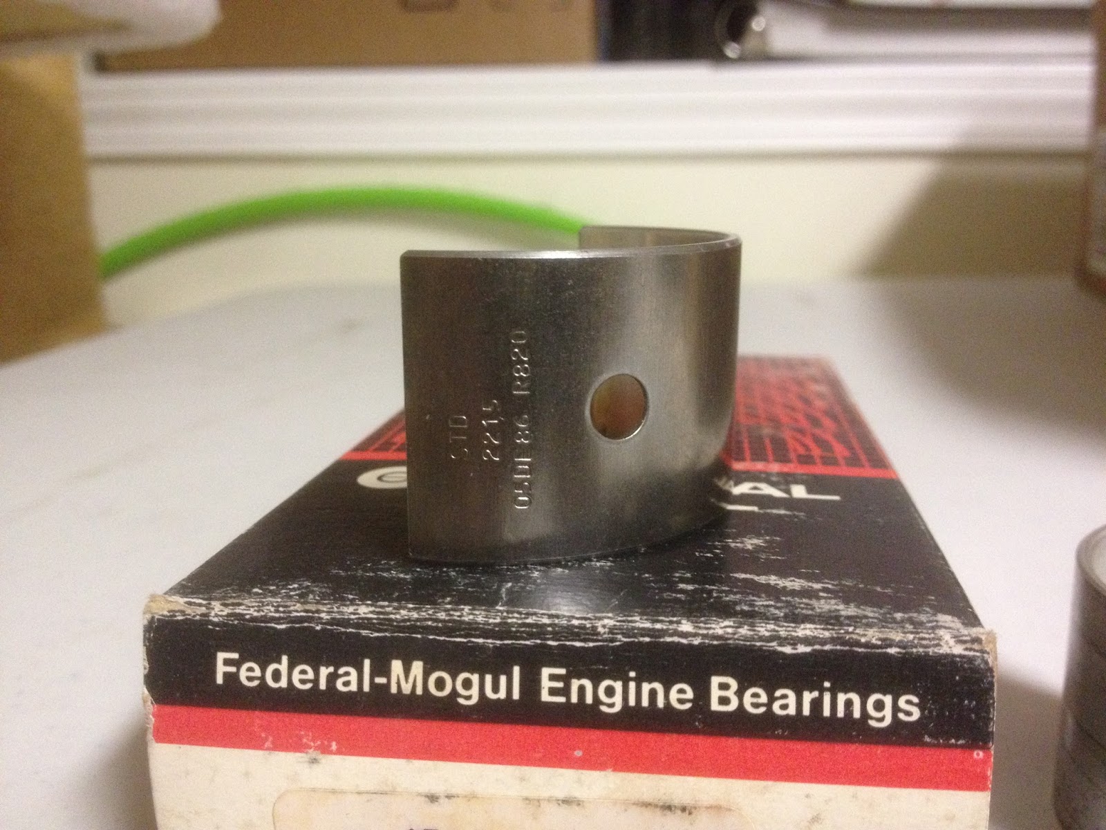
Once armed with a part number, I was able to cross reference that number and get a Federal Mogul number, which Rock Auto had available for about 15 bucks. Upon arrival, I checked all the dimensions, and I'm quite convinced that this is the bearing used in my engine. What does it fit? Why, a 1968 Nissan 520 Pickup, of course.

New bearing below, along with old one for comparison:


With that mystery solved, I'm cleaning my crankcase and crankshaft so I can have them tested for cracks. I don't expect to have that done this week, as I'm coming down with something nasty and don't feel like doing *anything.* Baby steps are still progress....

Saturday, January 7, 2017

Engine DISassembly (Part 4)

Between the holidays and lacking the proper tools half the time, it took me until now to finish gearing the engine apart. Mainly, the prop hub and crank gears were my main difficulties.  The prop hub I removed with the aid of a 3 jaw puller and two 4-foot extensions. One was a piece of angle iron drilled to fit the prop hub holes to keep the crankshaft from turning, the other was a 1" iron tube around a breaker bar.


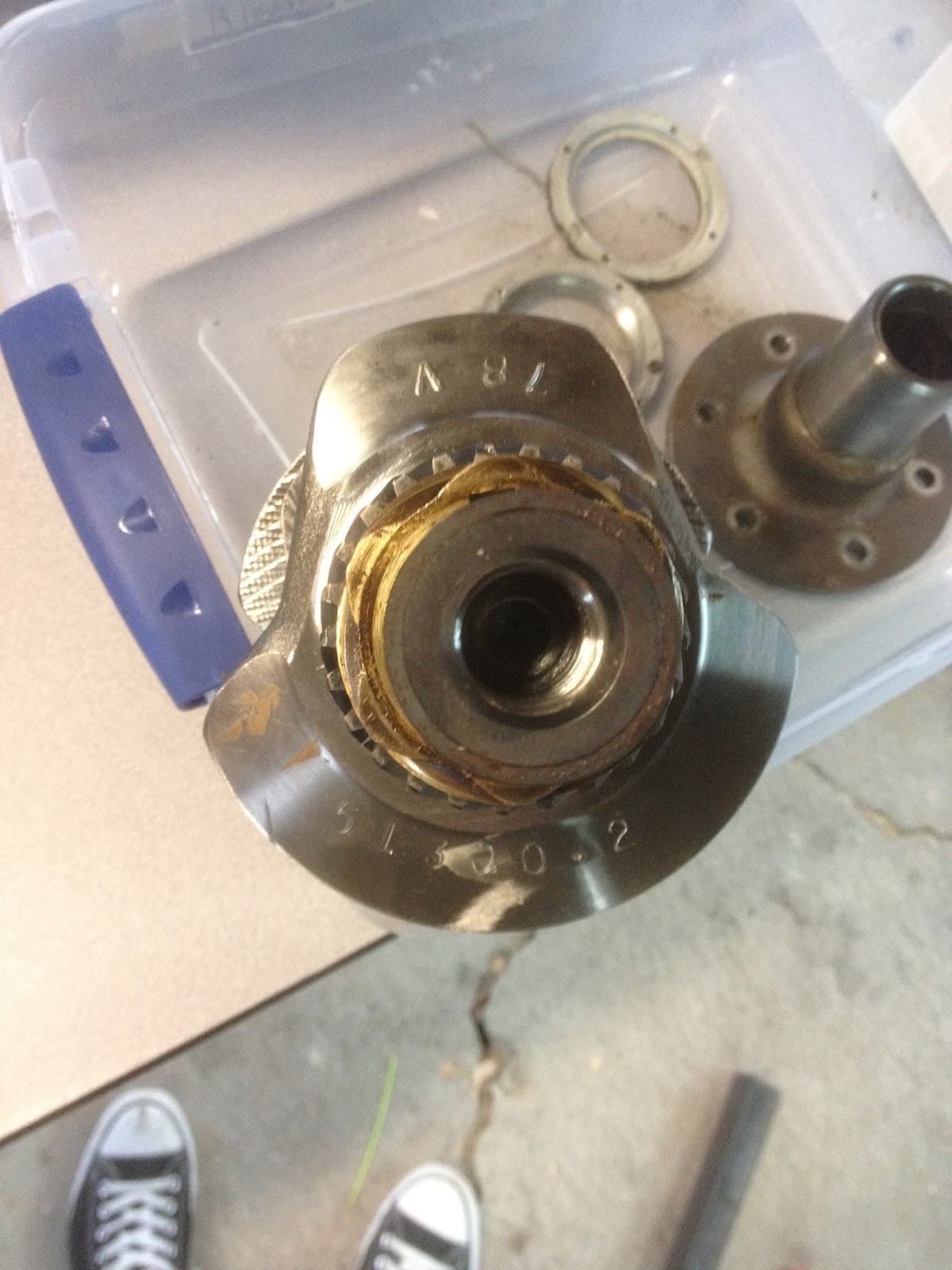
Once the prop hub was off, the next task was removing the cam and distributor gears. I machined a couple of pieces of aluminum and made a makeshift puller for those. Forgot to take  a picture of that, but it worked. This picture shows the crank before the gears were removed.


The next two pictures are the main bearings, which I'm having difficulty locating replacements for. It seems the 4th bearing (bottom of first pic, right-most in second) is something different than normal, and I'm not sure where to look to find one that matches.


Once I have that figured out, I'll start ordering parts and cleaning things up for reassembly.


Sunday, November 20, 2016

Engine DISassembly (Part 3)

I've been stuck trying to find the right tools for the last week or so, and then trying to find the time, but I finally made some progress. The pictures below show a collar assembly on the front of the motor, behind the prop hub. Apparently this setup is an anomaly - no one I spoke with was able to identify it. There are 4 screws that hold the front collar onto the back collar, which has one screw into each side of the case. Once I got the right size hex key, these came off and the case came apart.


These two collars house an oil seal around the crank shaft where it exits the case. My first inclination is to replace the seal, but I'm not sure what kind of damage I might do removing the prop hub. I'll have to think about it.


Once the case was split, I pulled all the cam followers and labelled them so I could replace them in the same locations. I'll be taking a lot of pictures once I've cleaned things up, but the camshaft looks like it's in great shape, so that and the followers will probably stay.


The inside of the engine wasn't as pretty a machining job as I'd expected, but everything turned nice and smooth when it was all together, so I'm not too worried about it. I haven't found a reason for the fine metal shavings yet, which makes me uneasy. 


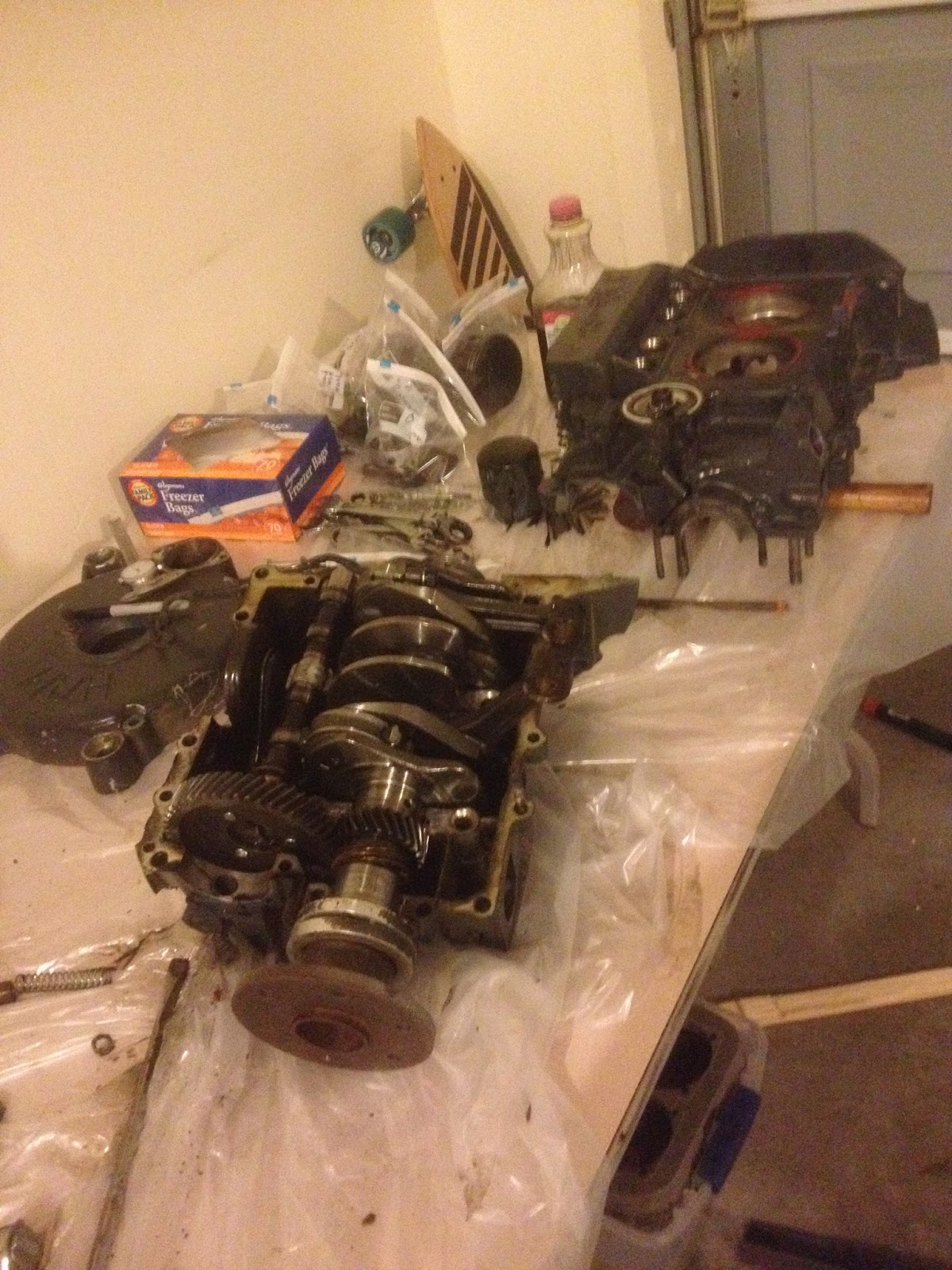
This is where I left it. There are only a couple of things left to do on the case before it can be cleaned up and inspected, and I don't expect the crankshaft assembly will be difficult to take apart. After that I can begin blueprinting, clean and inspect, order my parts, and put this thing back together.


Sunday, November 13, 2016

Engine DISassembly (Part 2)

Not much progress today, but I got a little further. I keep running into bolts that I don't have wrenches for, although hopefully that will stop soon. The main thing I accomplished today was setting up a table to work on, covered in plastic, and transferring the engine block from the stand to my new "workbench."


I got the pistons out, which ended up being easy enough... the Teflon buttons really were just floating in there, but I needed something sharp to stab the sides of the buttons to get enough grip to remove them. I forgot to take pictures of them tonight, but when I get into working on the cylinders I'll be spending about a paragraph on how crummy those buttons are.

Removed cylinders yesterday, but they're all laid out in order here. You can see the lower right cylinder has a lot of corrosion on the outside of it - the other three cylinders aren't corroded much at all. I think the corroded cylinder was a quick replacement to avoid a more serious rebuild earlier in this engine's life.


Another disappointing discovery when I removed the accessory case that covers the flywheel - the teeth are chipped pretty bad on about a quarter of the flywheel. Not messing around with that - I'll have to replace it.... unless they sell just the ring gear for it. I'll look into that...


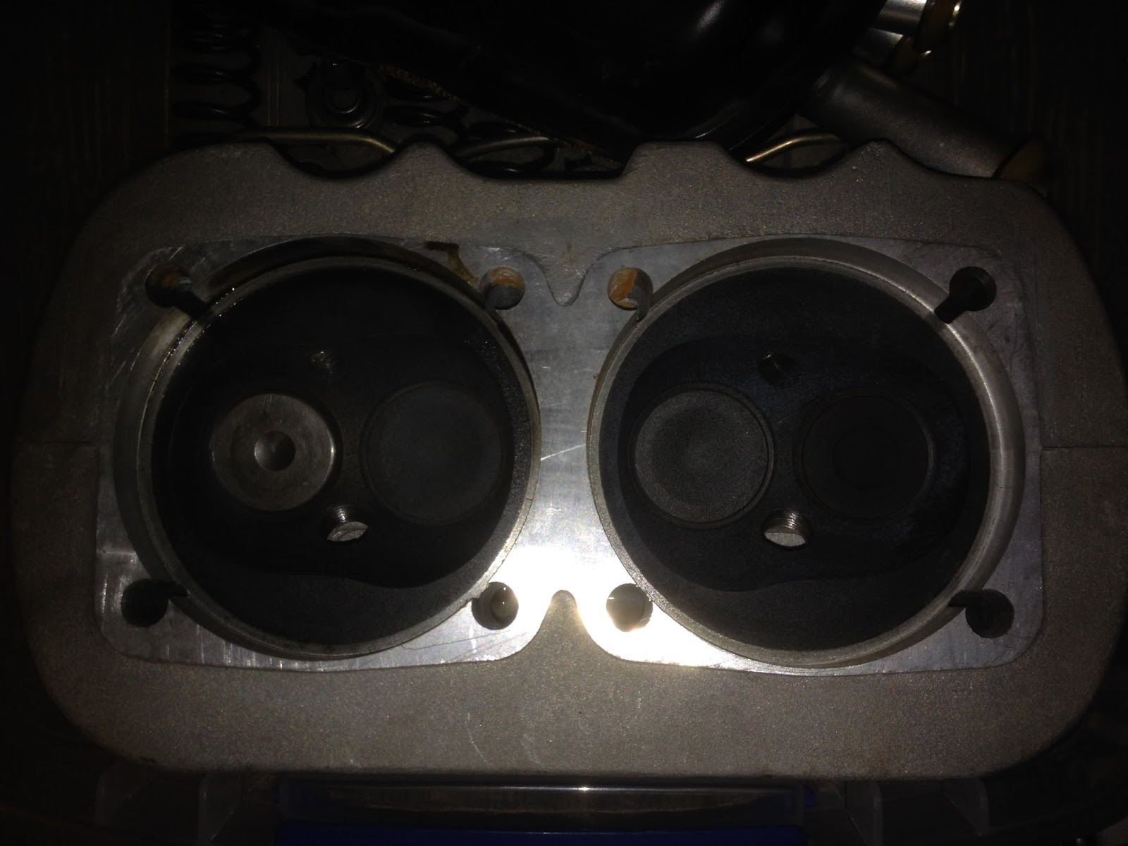
I also removed the valve springs, and while those all seem to be in good shape, I did notice that the same cylinder with lots of corrosion also has mismatching valves.... the valve on the far left below has almost no carbon deposited, not to mention is shaped different. I'll have to make a decision on whether or not that is an issue/will bother me enough to get new valves.


And here's the part where I don't have a big enough wrench - or rather, big enough socket. Not sure a wrench would be really effective, since this is recessed inside the flywheel.


Tomorrow I'll pick up some more specialty sockets, and hopefully make some more progress on tearing this thing apart. My goal is to have a semi-final list of parts to order by the end of the coming weekend, as I suspect some of the parts will take some time to acquire... especially if I wait until the holiday season.

Saturday, November 12, 2016

Engine DISassembly (Part One)

After a bit of a hiatus, I began tearing down the engine I intend to hang on the front of the plane. I'll be using a 2180 Volkswagen engine, originally built for aircraft use by Hapi a number of years ago. When I received the engine, it was mostly assembled, but I wanted to tear it down, blueprint everything, and rebuild it myself so I know it's done right. Besides, it's hard to powder coat an engine block with stuff attached. So today I finally started yanking stuff off.

Engine on the stand, ready for disassembly:


First I pulled the intake manifolds and spark plugs. I'm working on this engine away from home, so I lack most of my tools and all the helpful things like oil drain pans... Therefore, I used an empty lemonade bottle to catch the old oil. Seemed to work.


I pulled the valve covers, then the valve train. Sure looks a lot simpler than any other engine I've taken apart.


Next step was to pull the head, which came off pretty easily, along with one of the cylinders. The other cylinder wasn't much trouble.


The pushrods and pushrod tubes fell right out as well, and I hung onto those for referencing when I reassemble. I'll probably replace them, along with a good deal of other hardware inside.


The left head valve train was shimmed about .122 off of the head.

The right side wasn't any more difficult than the left. Valve train shimmed .088 on the right side.


I'd have liked to do more, but a little research is in order. The pistons are held on by a large pin, and that pin is usually captured by E-clips or similar devices. Whoever assembled this engine most recently used Teflon blocks that ride against the cylinder wall instead. Nice idea in theory, but if they ever wear down, there wouldn't be anything holding the piston pin in place... which would mean a catastrophic failure. I also noticed that one of the Teflon "buttons" had picked up some debris and scored the cylinder wall with it... another thing that wouldn't happen with the right hardware. I'll have to take some measurements and decide whether I want to hone that cylinder or replace it.

This is where I left off today.


You can see the Teflon "buttons" in the picture below - they're the white circles on the sides of the pistons. I have no idea how to remove these, unless they're to be pressed out with the piston pins. Time for research.