Showing posts with label prop hub. Show all posts

Wednesday, October 10, 2018

Prop Flange Extension

This will be a quick post - as part of my power plant setup, I'll be using a 4" aluminum spacer to help streamline my cowl around the engine. At my place of employment, I've got access to a CNC mill and a larger metal lathe, among other things. I was able to pick up a 5" diameter 6" long piece of 6061 aluminum for about $40 on Ebay, modeled what I wanted in CAD, then went to the manual lathe to turn it. I should have taken more pictures, but I didn't think about it; I do a fair amount of machining at work, and it all feels pretty routine anymore. The first picture I have is after I turned the stock down to final inside and outside dimensions, except for the face that will abut the flywheel. I set it up on a rotary table on the mill to get a bit more precision with the 6 prop-mounting holes, but that was probably overkill.


Spot drill, undersize drill, final drill, chamfer the edges. Not exactly rocket science. I intentionally left about an extra half inch on the end that I chucked up for the majority of the turning work, so that the marks left by the chuck wouldn't be on the final part. When I reversed it to turn the remaining face, I used some orange .050" plastic shim stock between the jaws and the part to avoid marring the finished surface. Turning the remaining face was straightforward, though I took light cuts to make sure I wouldn't pull the part out of the chuck. 


After the final lathe operation, I drilled the other 6 holes and cleaned up the part. Nothing left to do but put it away until the engine is ready to run... except test fit it on the flywheel.


Sunday, August 27, 2017

Fit so nice, I made it twice....

Actually, it was the wrong material, so I kicked myself a few times and bought a new flywheel. This time, a *forged* flywheel, not a *cast* flywheel. Had I the sense to do more research ahead of time, I'd have only made it once. Nonetheless, the new version is around 300% *less* likely to break apart during flight.

That's version 2. Same dimensions, but machines a lot more like 4130 than the first one.


In this blurry picture I'm pointing out the locating step for the flexplate. That way I know it's concentric. I did the same on the inside for the prop extension:


Now that this is finished, I was able to start test assembling the crankcase. First, the connecting rods on the crankshaft:


Drop the crank assembly into the case and add some nuts, torqued to spec:


It still rotated freely after it was torqued, so that was a good sign. No rubbing or clearance issues so far. The next step was to add the head studs and check the piston deck height. I painted my head studs to help avoid corrosion:


And then I added them to the pile.


I added a cylinder and piston, and started taking measurements. I used a .030" shim under the cylinder, which is how the engine came to me. I set up my dial indicator and rotated the crank to TDC for that cylinder.


Zero'd up the dial indicator (though the photo makes it look off);


Using a piece of steel rod I had laying around as a straightedge, I measure deck clearance + rod width at 0.428" or so.


The rod I used measured 0.314", which means my clearance distance is 0.114". That's a lot more than I want! VW specs are between 0.040" and 0.080". I went back and checked, and the old pistons are the same as the new ones, and the old cylinders were within a couple thousandths of the new ones. That means that this engine was assembled wildly out of spec.... which shouldn't be a surprise, but it was. And means more work; removing the shims brings me down to 0.084", which is out of spec (and 0.024" more than I really want.) That means I'll have to chuck each cylinder up on the lathe and turn it down to what I want. 

Unless...

...unless the heads are also anomalies, and have a much smaller chamber than normal heads, in which case the cylinders need to be extra long.... Bottom line, the new priority is get the heads reconditioned and blueprinted so I know what kind of setup I need.

There has been nothing straightforward about this engine. Armed with the knowledge I've gained from this process, I believe the next engine I assemble will be from brand new parts that I know the details on.

Monday, August 7, 2017

...And flywheel solutions!

I removed all the dowel pins from the crankshaft, which wasn't super difficult this time around... I think my holes are a light press fit, rather than the super-tight holes that were there originally. I'm not sure if that'll cause problems down the road or not; they are still a press fit, so load should (theoretically?) be transferred just as effectively.

The flywheel face on the crankshaft seemed to have zero runout when sitting in the crankcase, but there were a few problems with how I was taking that measurement that could have absorbed imperfections... so I decided to throw it at the lathe and check runout by painting the face with red dykem and scraping a tool along the face. The goal was to avoid removing any material, just rub the dykem off, and see if it was a gnarly edge on a dowel hole that was causing issues, or if the face itself was not perpendicular to the axis of rotation. I thought I took a picture of the result, but apparently this was another instance where my phone shut off instead of taking a picture... that's been happening a lot recently.

Anyways, the dykem was scraped off of about half the face, and the other half the dykem was still there; it made almost a perfect half circle of red and a half circle of steel. Now, the crankshaft was out about .0005 on each end, and I failed to document whether it was out the same direction at the same point in rotation; so when I did the math, I had to assume worst-case of the crankshaft being out a full thousandth of an inch. Even so, the pattern was much too extreme to blame it on a misalignment of that magnitude, so I turned a couple thousandths off the entire face. When I re-attached the flywheel, it was only out about 1 thousandth of an inch as opposed to the 8 I had before, so I put the dowels back in and put the flywheel back on. I put the whole thing on the lathe as an assembly, because I have to do a little more work on the flywheel.

Now to the part I have pictures of! The final flywheel is going to be two parts riveted together. The inside part will be turned from the original flywheel, and the outside is from a much lighter flexplate (which basically just positions the ring gear and transfers the load from the starter.) I cut the inside out of the flexplate on a CNC mill at work, since it was too big to turn on the lathe.


I also cut the outside off of the flywheel on the mill, but left it oversize so I could finish it on the lathe.


I could have programmed the mill to cut a circle, but I wanted to use a rotary table to get a true circle on the flexplate, since I can't touch that up on the lathe. Once I was set up to do that, it was just easier to do the same with the flywheel.

Once the flywheel and crankshaft assembly were on the lathe together, I started working towards the final shape. There's a step on the outside of the flywheel that needed to be turned flat with the rest of the face, and then a new step needed to be cut out from 5" diameter outwards to accept the flexplate. I've got the whole thing turned flat, and I used some red dykem to help me visualize where that 5" diameter will be.


It's been a little tough to find time to work on this stuff, but I think I see the light at the end of the tunnel. I have a few more parts on order, and once they get here I should be able to begin the reassembly process... which should be a pretty quick process, given how much documenting and adjusting and tweaking I've done *before* started to put it all together.

Tuesday, March 28, 2017

Rust removal sucks, Cleaning sucks, Painting sucks...

....but they're all pretty necessary if this engine is going to last. So I've been doing due diligence to remove corrosion, clean up, prep, paint, and heat treat all my engine components according to best practices as instructed by Bob Hoover and Tom Wilson. There's a fantastic resource online at http://www.eaa691.net/images/pdf/VW%20aircraft%20engine%20building.pdf , which is a hundred some pages on what to do, why to do it, and what happens when you don't. I've been just collecting parts and trying to get everything ready for the first trial assembly. Tomorrow I'm taking my crankshaft in to have it magnafluxed, and if it comes back ok I'll start putting stuff back on it. First the woodruff key and the gears, then the prop hub. The next step will be installing the bearings in the crank case, and dropping crank and camshaft, along with some associated hardware, inside and making sure it all turns the way I want it to. 

I got new cylinders and pistons, measured them, weighed them, cleaned them *very* well, and painted them black to prevent corrosion and encourage heat transfer. 

The cylinder on the left has wet paint on it, the cylinder on the right has been cleaned but not painted yet. I made sure to keep track of the cylinders, and marked them after they were painted so I could keep track of them.


As it turns out, the cylinders I designated as "A" and "D" were both 4.490" between the two sealing surfaces, whereas cylinders "B" and "C" were slightly shorter at 4.487". That's right on the edge of too much difference, but because I've got less than a half a thousandth of difference between matching cylinders, I'm not going to send them out to have them machined. Instead, I'll put both of the "long" cylinders on one side, so the heads will be able to seal correctly, and either make up the difference between the two sides with a .003 shim, or just not worry about it.... for all I know, once it's assembled, other tolerances may stack up and either make it a larger difference or even it out. That's why I'm calling this a "trial" assembly, because there may be adjustments to make after it's all together. 

I'm working on removing some surface rust on my prop hub with vinegar. Most of it came off after soaking for about two hours, but I'll give it another shot tomorrow after work. I still have a fair amount of cleaning to do on the engine case, which is about the last thing I want to do... but it's going to be the thing that's holding me up in just a few days, I think. By next week, I hope to be posting pictures of a freshly painted, partially assembled engine.

Saturday, January 7, 2017

Engine DISassembly (Part 4)

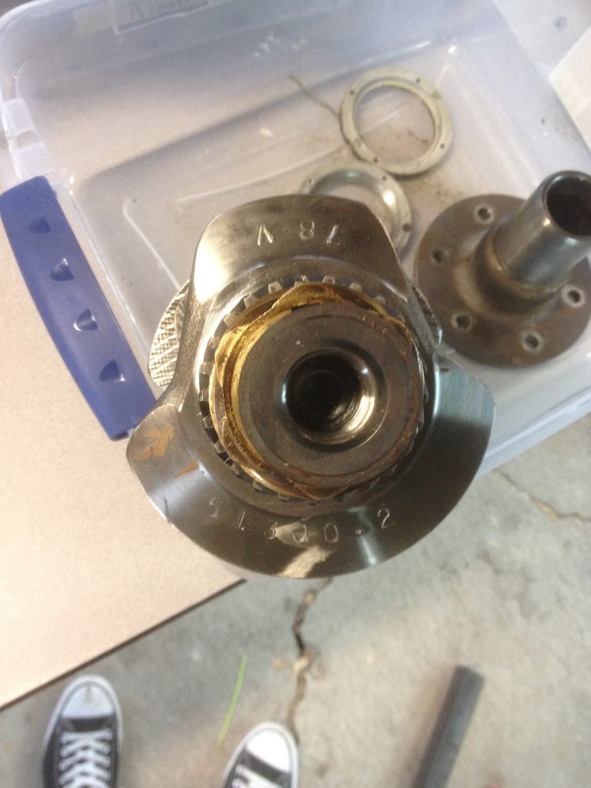
Between the holidays and lacking the proper tools half the time, it took me until now to finish gearing the engine apart. Mainly, the prop hub and crank gears were my main difficulties.  The prop hub I removed with the aid of a 3 jaw puller and two 4-foot extensions. One was a piece of angle iron drilled to fit the prop hub holes to keep the crankshaft from turning, the other was a 1" iron tube around a breaker bar.


Once the prop hub was off, the next task was removing the cam and distributor gears. I machined a couple of pieces of aluminum and made a makeshift puller for those. Forgot to take  a picture of that, but it worked. This picture shows the crank before the gears were removed.


The next two pictures are the main bearings, which I'm having difficulty locating replacements for. It seems the 4th bearing (bottom of first pic, right-most in second) is something different than normal, and I'm not sure where to look to find one that matches.


Once I have that figured out, I'll start ordering parts and cleaning things up for reassembly.


Sunday, November 20, 2016

Engine DISassembly (Part 3)

I've been stuck trying to find the right tools for the last week or so, and then trying to find the time, but I finally made some progress. The pictures below show a collar assembly on the front of the motor, behind the prop hub. Apparently this setup is an anomaly - no one I spoke with was able to identify it. There are 4 screws that hold the front collar onto the back collar, which has one screw into each side of the case. Once I got the right size hex key, these came off and the case came apart.


These two collars house an oil seal around the crank shaft where it exits the case. My first inclination is to replace the seal, but I'm not sure what kind of damage I might do removing the prop hub. I'll have to think about it.


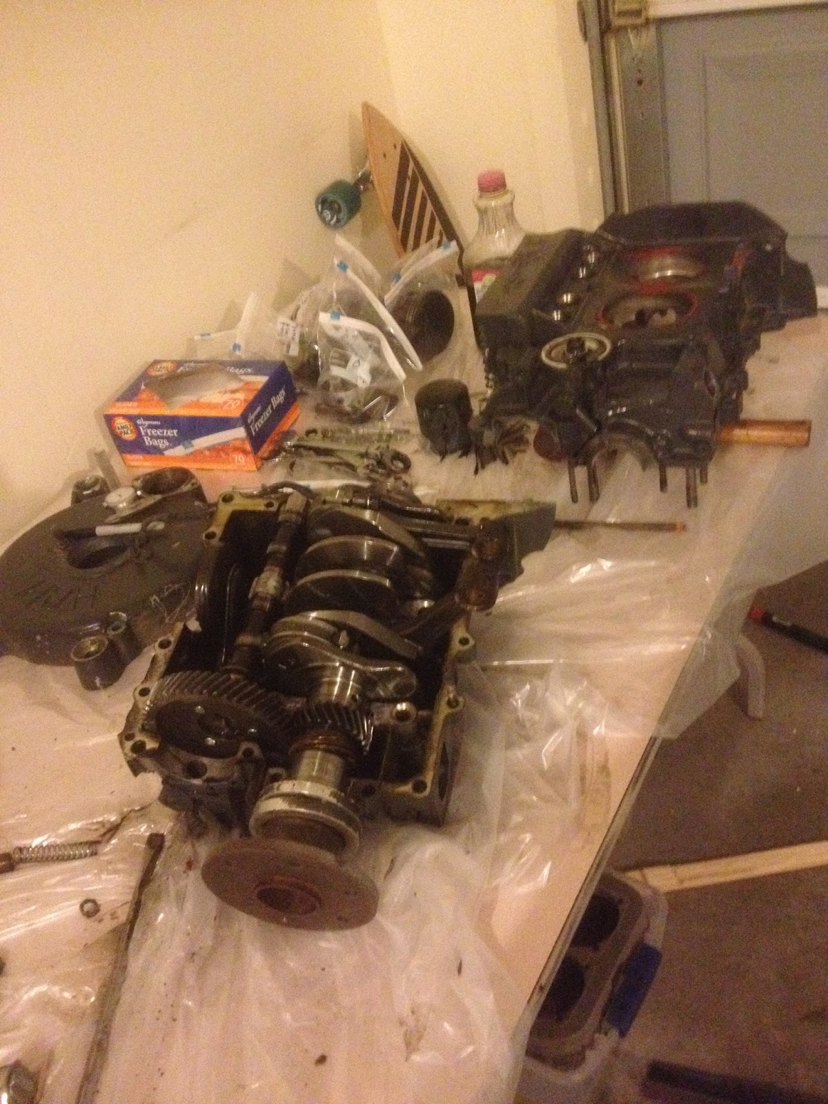
Once the case was split, I pulled all the cam followers and labelled them so I could replace them in the same locations. I'll be taking a lot of pictures once I've cleaned things up, but the camshaft looks like it's in great shape, so that and the followers will probably stay.


The inside of the engine wasn't as pretty a machining job as I'd expected, but everything turned nice and smooth when it was all together, so I'm not too worried about it. I haven't found a reason for the fine metal shavings yet, which makes me uneasy. 


This is where I left it. There are only a couple of things left to do on the case before it can be cleaned up and inspected, and I don't expect the crankshaft assembly will be difficult to take apart. After that I can begin blueprinting, clean and inspect, order my parts, and put this thing back together.