Showing posts with label aluminum. Show all posts

Wednesday, October 10, 2018

Prop Flange Extension

This will be a quick post - as part of my power plant setup, I'll be using a 4" aluminum spacer to help streamline my cowl around the engine. At my place of employment, I've got access to a CNC mill and a larger metal lathe, among other things. I was able to pick up a 5" diameter 6" long piece of 6061 aluminum for about $40 on Ebay, modeled what I wanted in CAD, then went to the manual lathe to turn it. I should have taken more pictures, but I didn't think about it; I do a fair amount of machining at work, and it all feels pretty routine anymore. The first picture I have is after I turned the stock down to final inside and outside dimensions, except for the face that will abut the flywheel. I set it up on a rotary table on the mill to get a bit more precision with the 6 prop-mounting holes, but that was probably overkill.


Spot drill, undersize drill, final drill, chamfer the edges. Not exactly rocket science. I intentionally left about an extra half inch on the end that I chucked up for the majority of the turning work, so that the marks left by the chuck wouldn't be on the final part. When I reversed it to turn the remaining face, I used some orange .050" plastic shim stock between the jaws and the part to avoid marring the finished surface. Turning the remaining face was straightforward, though I took light cuts to make sure I wouldn't pull the part out of the chuck. 


After the final lathe operation, I drilled the other 6 holes and cleaned up the part. Nothing left to do but put it away until the engine is ready to run... except test fit it on the flywheel.


Sunday, June 18, 2017

MORE Case and Crank prep...

It's been slow going lately, but progress seems to be taking place. I got lost in a lot of thought experiments and what-ifs, and (as is usually the case,) ended up right back where I started. So I cut the top off of the flywheel flange on the case, did a little bit of clearing on the inside of the case (some spots didn't seem to have more than a few thou of room for rotating parts), and used a Dremel to carve away a couple of channels for the engine mount in the back.


I also pulled all the aluminum plugs to get an idea of how much stuff was trapped in the case...


...And there was a lot! Much of that was from walnut blasting the case, but I found a good number of metal shavings as well. I'm glad I pulled the plugs... Next I tapped the holes for various pipe thread plugs, ranging from 1/16" NPT up to 3/8" NPT. I used a 1/2" NPT to tap a larger hole in the front for an oil temp sensor, because I've read bad things about the current temp sensor location (near the flywheel end of the case) actually reading quite a bit lower as a result of not being in a high-flow area. The new place is directly in the oil flow as it enters the oil pump, so it'd be hard to get a better reading than that!

Drilling and tapping the magnesium was quite easy, actually... in that the magnesium tapped without much force. There were a few places that I had to tap a few threads, then grind the tap down, then tap a few more, then grind, back and forth a few more times until the plug fit the way I wanted it to. There's one hole that I may have tapped just a little too hard and began to mess up the threads, but the plug threads in just fine and seems to have full contact along the entire length and circumference of the plug, so I'm going to leave it.

Now that all of the holes are prepped, I'll pull all the plugs out for another cleaning session. The last step will be to file a notch in each of the plugs so I can swage the case metal into those notches as a final insurance against the plugs working their way back out.


I forgot to take pictures, but I drilled the crankshaft for a couple more dowel pins. When I received it, it only had two, which was probably fine running the prop off the other end, but I'm not comfortable only using two running it with the prop hanging off the flywheel. So I drilled two more holes, reamed them, and tried to put the dowels in.... oops! One of the holes is *way* too loose! So I ordered a 11/32" drill bit blank, cut it down to the right length to be a dowel pin, and re-reamed the hole to be a press fit. This really isn't a bad plan anyway, as it keeps my flywheel aligned the same way every time it's reassembled, and the only extra work I'd have to do on a new flywheel is drill one hole slightly larger.

Upon reassembly of the flywheel and crank, I realized the flywheel is running about 60 thousandths out of true at the outermost edge. Not cool at all. So my next step is to remove the dowels and see if the crank face is out, but my bet is that somewhere along the way some burrs crept up and are keeping the crank from seating correctly. At least, I hope that's what happened... otherwise it's back to the machine shop.

Thursday, February 23, 2017

Slow progress, but promising results!

A few months ago, my wife and I relocated to Rochester, NY for work, and to be closer to her family.
A small part of my new job is machining odd parts on a Tormach 1100, a 2.5 axis CNC mill. As a result, I'm now able to make *much* nicer and more complex parts than I could on my drill press in my shop back in PA. Which is really handy, since I ruined a couple of custom pieces taking this engine apart.


This is a two-piece housing that holds an oil seal. All of the information I could gather said that this should be attached in a way that prying and application of heat would allow its removal. All of that information was incorrect, as it turns out. Several #6 screws, hidden by RTV sealant and covered with paint, held this assembly on. I managed to bend it during my first failed attempt at removal, but even worse, I scraped the sealing face pretty bad with the screwdriver I was using to pry it off. As a result, I needed to replace both pieces.... and it just so happens I now have the tools to do so.

I didn't take a lot of pictures, but here's a shot of an aluminum blank next to one of the (almost) finished pieces:


I think the originals were turned on a lathe, based on the finish on the old parts vs the finish on the new parts. (Admittedly, I am not what most would call a competent machinist, so maybe I just failed to produce a quality part.) However, I think the new pieces will work out just fine.


According to the book I'm reading, "How to Rebuild your Volkswagen Aircooled Engine," Tom Wilson says the best way to clean the aluminum/magnesium engine case is with regular old soap.... with phosphate. Probably wasn't hard to come by when the book was written, but now it seems nobody sells it. I'm going to try regular old soap without phosphate, and see what happens. I'll be taking my crankshaft in next week to have it magnafluxed, and if it passes I'll be placing my big order for engine parts. My hope is that the engine will go back together pretty quickly, since there was no apparent damage and it ran ok before. 

As explanation for my apparent lack of significant progress, allow me to placate you with a picture of my son, who was born a few weeks ago, and has been eating up all of my time. Strangely, I don't mind....


Saturday, January 7, 2017

Engine DISassembly (Part 4)

Between the holidays and lacking the proper tools half the time, it took me until now to finish gearing the engine apart. Mainly, the prop hub and crank gears were my main difficulties.  The prop hub I removed with the aid of a 3 jaw puller and two 4-foot extensions. One was a piece of angle iron drilled to fit the prop hub holes to keep the crankshaft from turning, the other was a 1" iron tube around a breaker bar.


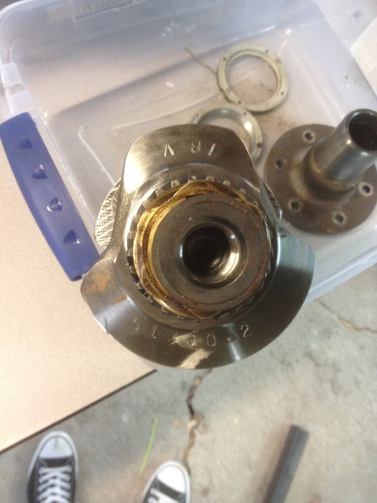
Once the prop hub was off, the next task was removing the cam and distributor gears. I machined a couple of pieces of aluminum and made a makeshift puller for those. Forgot to take  a picture of that, but it worked. This picture shows the crank before the gears were removed.


The next two pictures are the main bearings, which I'm having difficulty locating replacements for. It seems the 4th bearing (bottom of first pic, right-most in second) is something different than normal, and I'm not sure where to look to find one that matches.


Once I have that figured out, I'll start ordering parts and cleaning things up for reassembly.


Friday, August 19, 2016

Outer Wings (Part 6)

Continued from Outer Wings (Part 5)
Today I finished sanding the wing to shape. My micro trailing edge is nice and solid, and I sanded the overlapping fiberglass on the leading edge down nice and smooth for the next couple of layers. I hand planed the spars down to slightly below the airfoil contour, which was much easier after I took five minutes and sharpened the blade. I didn't take many pictures, but I did document how I'm prepping the sump drain as well as the WAF cut-outs in the foam. The cut-outs each get some one-on-one time with a Dremel, so that the foam is slightly recessed. Next I take a piece of pre-layed-up fiberglass and cut it to fit the cut-out.


Once I've got all four cut to fit, I mix up some micro and apply it to the foam, then set the fiberglass in the cut-outs. I'm not too picky about how it lays, but generally I try to make it as close to the airfoil contour as possible, erring below rather than above.

For the sump drain, I start by attaching a circular piece of duct tape over the hole. Then I use a really thick micro to build up from the aluminum block to the airfoil contour. While the micro is in the "green" stage, I use a Forstner bit to generate a nice circular hole down to the aluminum block where the duct tape is, which gets removed (because it's now all gummy and may not keep the resin out during the big layup.)


I'll replace the duct tape before I do my layup. I'm prepping for that by cutting templates out of plastic 2 mil drop cloth, then cutting the fiberglass from that. If everything goes well, by this time tomorrow the wing will be finished and off the plane.

Wednesday, August 17, 2016

Pitot (Prandtl) Tube

Let me start off by saying, it's probably much easier to just buy a pitot tube. But one of my major motivations for a wide variety of my hobbies is the voice in my head that says, "I can do that, and I can probably do it better*." So in the spirit of not accepting the status quo, I decided to see if I could make my own without buying any new tools.

Let me also explain that a wide variety of homebuilt aircraft builders find inexpensive ways around all sorts of problems, and this is one I've seen a lot of creativity with. From just soft aluminum tubing to VW pushrods to all manner of "I had this laying around the house" DIY, it's been proven that with a little trial and error, you can make almost anything work if you try hard enough. However, due to the speed at which this plane travels, and the amount of trouble I would be in if my airspeed indicator decided to stop working due to a bent/broken pitot tube, I felt it a worthwhile pursuit to build a very sturdy, very likely to be accurate structure. I didn't design anything new, just copied other designs that made sense to me, focusing first on strength and second on aerodynamics. With that out of the way, here's what I did.

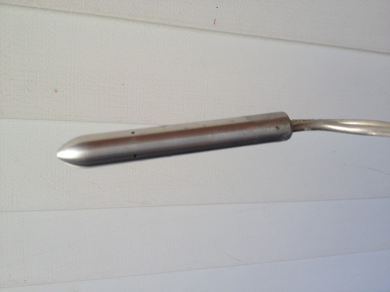
I determined that 2024 aluminum was a good material to use, as it's quite strong and still quite light. Also, because it's "just aluminum," I was willing to try turning it on my wood lathe. I've turned wood for about 7 years, which certainly doesn't make me an expert, but I've had the pleasure of playing with a lot of different species. Aluminum is much easier to turn than many of them. It takes much longer to shape, but there's no grain to it, so I had no troubles turning it with even my cheap lathe chisels. I started with a 3/8" rod, cut it to length, trued up the ends in the lathe, then drilled a 3/16" hole through it, and finally turned one end to a point. This would have worked fine, but...

One of the difficulties with an airplane is, you're moving through the air. The difficulty comes in figuring out just how far away the ground is. We know that, as a general rule, air is less dense the higher we are. The altimeter in an airplane counts on that fact to display its altitude. An altimeter measures air density by measuring air pressure, but where do you take that measurement? Inside the airplane isn't a safe bet, as air currents can vary wildly and cause massive pressure shifts depending on airspeed, air vents, and where you put your flight bag. Outside the airplane, the air is moving very rapidly, and if the static air source is tipped slightly into *or* slightly away from the direction of airflow, your reading will be very very wrong. One of the more common methods is to place your static source, or port, on the side of the fuselage, where the port will be perfectly perpendicular to the airflow. If you fly the airplane in a slip or skid, however, your measurement will be off again, so you need another port on the other side of the plane so the measurements can even out. One of the more elegant solutions to this is called a Prandtl tube.

A Prandtl tube combines the functions of a pitot tube and a static port, and does so in a way that, theoretically, is less prone to error under normal conditions. Do other methods work? Just fine, as a matter of fact. However, for this airframe, a number of people have used a number of methods, and it seems that what works for this guy causes major problems for the next guy. A Prandtl tube should work on any airframe, as long as it's placed in a free airstream. I stole a diagram from Wikipedia:


Pitot and static, measured from the same spot. How to accomplish this with minimal effort?

First, I got a 5/8" 2024 aluminum rod and turned the shape. Next, I drilled it down the center with three drill bits: 1/8" bit from the front straight back about an inch, 3/16" bit from the back all the way to the start of the 1/8" hole, and 3/8" from the back about an inch shallower than the 3/16" bit.


Next, I drilled 4 1/16" holes about 2 inches back from the tip, each 90* from each other, so I ended up with a hole in the top, bottom, and each side of the tube. I then took some 3/16" OD aluminum 3003 soft tubing I had laying around (after quite accidentally ordering 25 feet of the wrong size) and floxed a piece all the way down into the 3/16" hole, and then floxed another piece about an inch inside the large hole, then used more flox to seal the large chamber. What I ended up with looks about like this:


The red is the tubing, the green is the flox. Only two of the 4 holes are shown. Once that all cured, I hooked it up to my airspeed indicator and altimeter and took a drive, holding the Prandtl tube out the window. It seemed to work poorly, until i disconnected the altimeter. Turns out the altimeter leaks like a sieve, but the Prandtl tube works like a charm. I was getting very consistent readings, even angling the tube 15 degrees or so from straight on into the wind.


Ok, so it works. Now all I had to do was build a strut to hold it ~4" below the leading edge of the wing. To accomplish that, and because I was feeling picky, I printed off a low drag NACA airfoil (NACA 0021, I believe) and cut out two wood templates, glued them onto a piece of foam, and sanded that foam to shape. Then I glassed the foam, drilled a few holes to attach the Prandtl tube and to allow the two 3/16" tubes to run up the center of the foam, and glassed that all together.


After it had all cured, I put on a couple more layers of micro, building up the trailing edge, fairing in the transition between strut and Prandtl, and then sanded it nice and smooth. It'll stay that way until I'm ready to attach it to the plane. (Obviously the last picture is not sanded smooth. I'll update this with another picture once it's finished and attached.)


*Better, more often than not, means good enough for less money, or better for my specific application. If I really thought everything I did was better, I'd be a businessman (and probably a very, very broke one at that.)

Wednesday, March 30, 2016

Rudder Pedals and Elevator Brackets

I've been making small amounts of progress here and there. I'd been putting off the rudder pedal swingarms, because I wanted them offset to work with the offset seating. In order to generate more shoulder room, the pilot's seat will sit 3" forward of the pax seat. That doesn't sound like much, but it causes shoulders to overlap rather than push against, which makes things much more comfortable. My shop really isn't set up for metal work, so cutting, grinding, and jigging this 4130 has been a challenge.


This was my first jig attempt, and while I did get it to work well enough, it was a huge hassle. The second jig turned out a lot better, and was much easier to build.


These were sent off to be welded, and are now ready to be cleaned and painted. I'll be cleaning and painting the steel parts of the control sticks assembly at the same time.

While I was set up for it, I went ahead and cut my elevator pushrods to length. I have a 5/8" rod from my control sticks to a T lever, which transitions to cables, which run back to another T lever and a 3/8" rod to the elevator.


The pushrods are not yet connected to the rod ends in the picture, but that's not an oversight. I wanted to hook everything up before drilling holes and riveting, to make sure the length was right!

The main reason for my slow progress has been my own work in adjusting existing designs to fit my needs. Specifically the brackets/T-lever assemblies. It takes me a while to fabricate the metal bits, so I try to make absolutely certain that I don't have to re-make any parts due to unforeseen problems.  A few of my sketches are below, showing the bracket and T-lever setups.

This is a 4x scale drawing of my forward T-lever setup. From left to right: sintered bronze (SB) bushing, 3/4" aluminum spacer, aluminum T-lever, SB bushing inside the T-lever, 3/4" spacer, SB bushing. I have SB bushings on both ends, so that's what will contact the bracket, and I have a SB bushing through the actual lever itself to facilitate smooth rotation.


Next is a 1:1 drawing of the rear T-lever, which also incorporates an arm for counterbalancing the elevator. I will preempt this drawing by saying, I did not use this design. Rather, I adjusted it with spacers.


And here's a 4x drawing of the center of the assembly, or the pivot point:


From left to right: SB bushing, T-lever, 3/4" square tubing for counterbalance, 1/4" angle, SB bushing. The problem with this design is, the cables will rub the counterbalance arm when it pivots. As a result, I'll be adding a spacer between the T-lever and the 3/4" square tubing. 


This gives you a better view of the problem. The second and fourth "nut" from the top will have cables attached, and anytime the elevator isn't slightly up the counterbalance will intersect one of the cables. Adding an 1/8" spacer to the pivot point and the pushrod point should give me enough clearance.... or maybe 1/4". I'll be mocking this up *not* in the plane, to make sure I get it right, before I start drilling holes in the wrong spots. Anyway, I hope to have most of this finished after this weekend. 

Tuesday, February 23, 2016

Control Sticks (Part 6)

Continued from Control Sticks (Part 5)
I finished cutting, shaping, and drilling the aluminum brackets, as well as the nylon bearing surfaces. I was very careful to make sure there would be no slop in the system when I was drilling the holes. Somehow, once again, I managed to order the wrong size hardware, so everything is temporarily assembled with other bolts I had on hand. I'm going to write up a list, or maybe a spreadsheet, that lays out what length bolt is ideal for various depths of material, because I can't seem to get it right. I test assembled everything on my workbench, and marked my layout so I could transfer the brackets to the plane.


Next I marked on the front spar where I wanted the brackets to be, lined them up and clamped them, and started drilling holes. I drilled one hole at a time, making sure everything lined up before committing to another hole. I really didn't wanna screw this up!

Everything in place, at least temporarily:


As you can see, I left the actual sticks long because I wasn't sure what length I'd want. I'm going to have to give them both a slight bend so they'll have enough throw to clear the front spar, whilst remaining far enough forward to be comfortable. I'll have to disassemble when the correct hardware arrives, and I may paint everything for corrosion resistance. I also need to redo the cables - only one of the three cables has a turnbuckle, which means if the cables ever stretched or needed adjustment, you'd have a heck of a time getting things realigned. Regardless, I'm much happier with this setup - lower profile, much better geometry, and working on this gave me an idea for a really simplistic aileron trim that'd be pretty easy to implement.


Monday, February 22, 2016

Control Sticks (Part 5)

Continued from Control Sticks (Part 4)
I got my brackets and sticks back from the welder today. I forgot to take a picture of the bracket, but this is how I fitted and attached the aluminum "fingers" to the sticks for welding.

I cut a square wooden peg to match the OD of the aluminum tube, drilled a hole where the aileron cable connection will be, then chucked it up in my lathe and turned the other end down to the ID. I turned far enough along the peg to set the depth of my jig.


This is the jig inserted into the tube, with the fingers already welded on. A small C-clamp held the fingers to the tube for tack welding, and then was removed for the full passes.


I realized after I got these sticks back that I had forgotten to mark where I needed the other set of holes. The main problem I faced was getting the holes in the center of the tubing and lined up with the existing holes. My drill press vise is just far enough off of level and plumb that I didn't trust it, so instead I used a speed square to find the center on both sides, then drill and ream the holes.


I drilled and tapped a length of ¼" 4130 tubing to connect my two control sticks along the horizontal axis, which turned out to be a little bit of a trick. I chucked the tubing in my lathe in order to drill it out so I could tap it, then locked the lathe up and tapped it by hand. I didn't drill quite far enough on one end, so I broke the tap... luckily, enough was sticking out that I could grab it with pliers and screw it right back out. Another trip to the hardware store for a new tap, and I was finished. I threaded in two AN42B "eye bolts," and it was ready to connect.


The last of the metalwork for the control sticks was to make the mounting brackets. I needed a set of brackets to hold the control sticks, and a set of brackets that will mount to the back of the rear spar where the pushrod will transition to cables. I did some adjusting to Mark Langford's drawings for the former, and did some math and drew up the latter on some graph paper. Here they are, attached to ⅛" 6061 T6 aluminum angles, but not cut out yet. I started by drilling all the holes, since that can be a difficult procedure once everything is cut out.


Tomorrow I hope to finish the mounting brackets and begin assembly in the fuselage.
Continued in Control Sticks (Part 6)

Thursday, February 18, 2016

Control Sticks (Part 4)

Continued from Control Sticks (Part 3)
I made progress on a lot of little things today. I laid out, drilled, and cut the nylon bearing surfaces for the control sticks. Forgot to take pictures of that. I redesigned the brackets that'll bolt to the front spar, because the plans I'm using account for a flap design I'm not using. I'm still waiting on the material I need to fashion the brackets, so I couldn't work any further on that. I also drew up plans for the bracket assembly to hold the bellcrank behind the rear spar,  where my pushrod will transition to cables for elevator control.


I've found no matter how much I work with various CAD software, the easiest and fastest way for me to design things is still on paper. (Partly because I usually spend about an hour fighting with my printer when I want the finished design printed to scale.)

I'm not a very proficient welder, and I don't have the right tools, so I sent my jigged-up assemblies out to be welded. Once those come back and the rest of my material shows up, I'll be able to finish this project and move forward. I believe I'll finish the rudder pedal assembly next. Sometimes I feel like I'm going to run out of work that isn't fiberglassing before it warms up, but I'm well known for taking *way* longer than I say I will to finish projects.