Saturday, June 18, 2016

Wing Walks!?

I've ordered and received a whole bunch of foam from Dynamic Systems (aka SunMate), which I chose as a crash safety measure as much as I did as a comfort aid. I've been cutting away and shaping, but I've gotten to a point where I need to be doing a lot of sitting in the seat and seeing if it's comfortable yet. Only problem is, the plane has no wing walks.... and as challenging as it was to get in the plane standing just on the rear spar, that was preferable to setting up a makeshift seating setup outside the plane. I decided, since I need wing walks eventually, I might as well get them knocked out now so I can get this seating stuff taken care of.

The previous builder had glued and shaped the foam for the top of the inboard wing, and laid what appeared to be one layer of FG on it. I didn't want to disrupt the shape of the wing, and I didn't want to completely start over, so I decided to try and add a wing walk structure without disrupting anything I didn't have to. First step was to flip the plane over and get a good look at the underside.

The previous builder had used a single sheet of 1" foam, and cut slits halfway through it about every 2 inches in order to allow an easy curve to the shape of the wing. This was about how far apart I wanted to put supports, so I started by using a razor blade to extend the slits all the way to the fiberglass skin. I made my wing walk 12" wide, and it runs from the front spar to the rear spar. I dug out the foam in the slots, then cut another slot for a support to run lengthwise from spar to spar. I used ⅜" a/c plywood for the long support, and 3/32" a/c plywood for the rest of the supports. All the supports are 1" wide.


The last step before epoxy(or so I thought...) was to cut slots in the foam for two ½" spruce blocks to (drastically) increase the gluing area for the ⅜" main support.

When I test fitted the supports, I noticed that my long stringer (which was cut very, very precisely to the airfoil contour) didn't touch the skin in a lot of places. As in, ¼" to ⅜" gap. A closer inspection of the wing showed the problem; the foam and fiberglass had sunk, or had been attached too low at the rear spar, and the wing shape was not preserved except at the two wooden templates. I had to think for a couple days to come up with a solution to that one, but I think I came up with a good one. 

I used my hot wire foam cutter and two wooden templates to cut two 12" wide foam templates, one for each side of the wing skin. The outside template I left long enough to rest on the spars, while the inside template I cut about 1" too short so it'd be able to easily drop in place once epoxy was curing. I used some highly sophisticated and carefully calibrated bracing structures (read: spare tires) to support the outside template and, once it was in place, I mixed up my epoxy with some micro to fill in gaps and started inserting all of the supports. Once the supports were all in place, I placed the inside template (with plastic trash bag to isolate it from the epoxy) on the wing, and added a good amount of weight.


When I came back the next day, I was *very* happy to find that the setup had worked perfectly. My wing was now the shape it should've been (or, much closer to it) and the supports were all in place and holding. I mixed up more micro/epoxy and filled more gaps, then laid up two layers of FG and placed them over the structure. Although I'm not sure it was entirely necessary, I repeated the process of weighting the template over this to make sure it all cured with the right shape.


I did the other side the same way, and although the previous builder cut a few more slots in the other side, the results were similar:

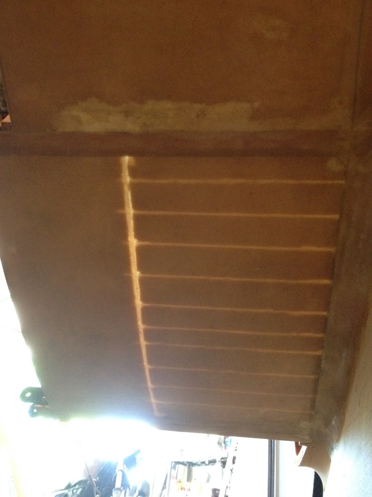


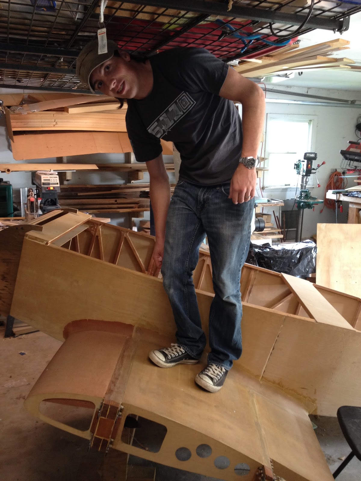
The final result was solid. I'll be adding one or two more layers of FG to the top of the inboard wing, but it's already strong enough for me to stand on unsupported with no perceptible give. I'd call this a success.

Friday, June 17, 2016

Seats (Part 3)

Continued from Seats (Part 2)
I've spent the past few weeks making some solid progress, although it doesn't feel like it. I cut the carbon fiber seat pan to its rough shape, and cut the channel for the elevator pushrod to run through. I've also got a piece of foam cut to shape as a former for the carbon fiber to lay over the channel, creating a tunnel to protect the pushrod from debris (and from being stepped or sat on.)


I wet out two layers of CF, wrapped them around the foam tunnel former, and slid that into the slot I cut.


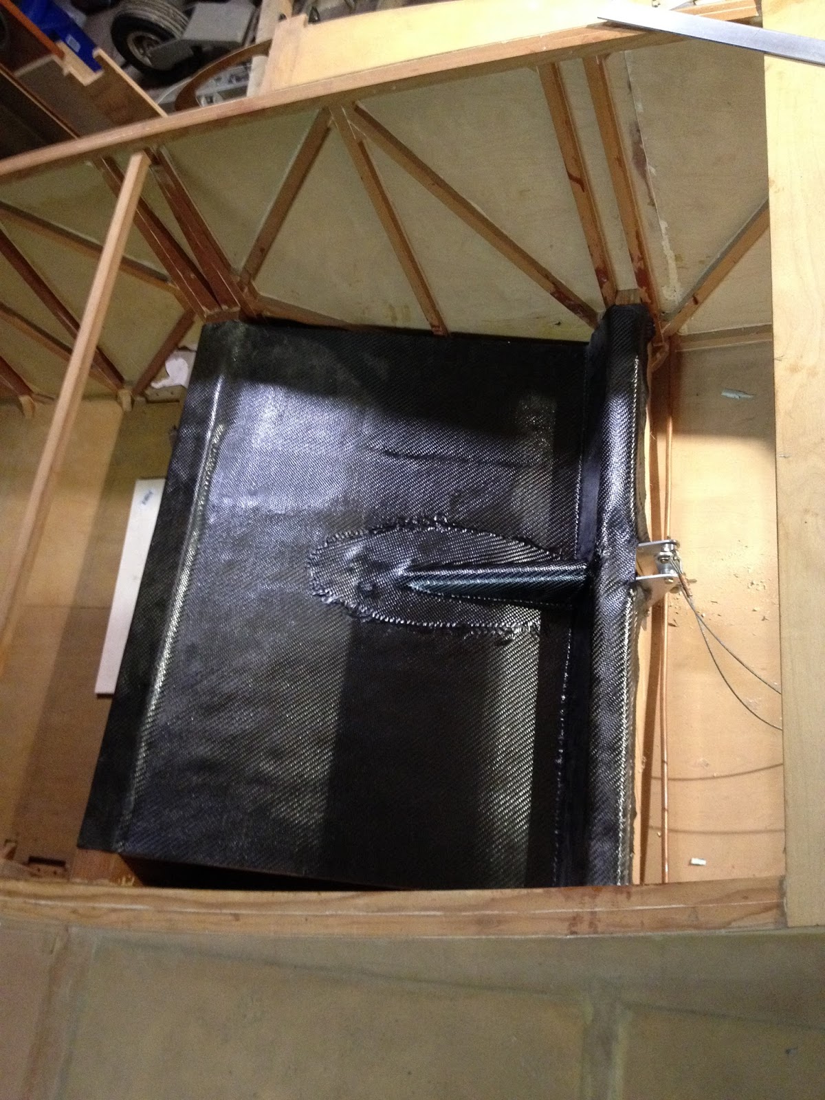
Once that cured, I removed the foam and flipped the seat over. I wet out two more layers of CF (for four total) and laid those over the tunnel from the last step. This would have created a void at the forward end of the tunnel, so I filled it with a really thick micro mixture ahead of time.


 It looks in the picture like the CF over the tunnel has sharp edges, but they're all quite flat and smooth in real life.

I tried to do the seat back next, using some left over foam from my wing tanks. That was a disaster, and I mostly just wasted time and resources on learning how *not* to lay up fiberglass. I may write up the long version at some point, but I'm not sure anyone else is dumb enough to try it as many times or as many ways as I did before giving up (or getting it right.) Long story short, plastic bagging is a perfectly viable fiberglassing option, but like everything else in fiberglassing, it has to be done just right. So far I haven't figured out how to do it just right. So I'll go back to fiberglassing the way I usually do, because I really want repeatable results (and I really want a seat back!)

Saturday, May 28, 2016

Seats (Part 2)

Continued from Seats (Part 1)
I spent a lot of time prepping for the actual carbon fiber layup. Some of my brackets didn't fit quite the way I'd like, so I did a lot of fiddling to get everything right. After that, I trial fitted and then shaped the seat to fit exactly how I wanted it.


Once I was satisfied, I began using duct tape and plastic drop cloth to protect the fuselage from any epoxy drips.


After one more trial fit, I got ready for layup. Two layers on the bottom, two layers on the top, each with one layer 45 degrees to the other. I wet out the carbon fiber between two sheets of plastic in order to keep the carbon fiber layers from shifting. It didn't work as well as I hoped, and the epoxy was beginning to set up before I had it on the foam. Apart from that, the process went fairly smoothly. Seat went onto the bottom layers, which was then lifted into position in between the spars. The top layers were then placed on top, and everything was pressed together and smoothed out, then left to cure.

Final trial fit:


With carbon fiber and curing:


After it was cured, I gently but firmly removed the seat from the plane. Next I'll need to cut out and add a tunnel for the elevator pushrod, holes for the control sticks, and then work on the back of the seat.

I found a picture of the plywood cutting process, and am uploading it just for my record below.


Wednesday, May 25, 2016

Seats (Part 1)

After two solid months of doing little nothing projects here and there and generally not accomplishing very much, the weather finally got nice enough to start doing some fiberglassing. So I decided to build my seats next, because 1. it's a smaller fiberglass project to get me back in the swing of it before I tackle the wings, and 2. once I have the seats in place I can set my rudder pedals, my control sticks height, canopy and therefore aft deck height, and also sit on it and make airplane noises. I'm using carbon fiber for its strength to weight ratio, and because the seat giving way in flight would cause the airplane to be uncontrollable, so I want it as strong as possible. At this point I intend to build as much of the plane with vinylester resin as possible, because it cures very fast compared to just about every viable epoxy I've tried. However, there's some solid research that suggests vinylester doesn't bond well with carbon fiber, so I'm using West Systems epoxy instead. West Systems is fantastic stuff, but it takes about 6 hours to cure at 70* F, and that time goes up dramatically as temperature goes down. This week is all warm days, so I'm gonna try to knock this out before the end of the week.


I started with ½" foam, sliced into 2" strips. I epoxied 3/32" plywood in between each strip, so the strips of wood and foam are oriented length-wise in relation to the aircraft.


Once that had cured, I cut the panel into two pieces, one to match the seat back, and one to make up the flat bottom of the seat. I also built about the crummiest looking jig you could imagine to get the angle of the two pieces right, but it worked out just fine for my purposes.


I didn't get a good picture of it, but I cut slots right next to each of the wooden stringers in both panels, then used that same 3/32 plywood to make biscuits to fit in them to really strengthen the joint. Once I had them all prepped and trial-fitted, I mixed up my epoxy and went to work. Obviously no pictures of the process, but it was messy and the epoxy gets hot in the cup pretty quick when it's 80 degree weather. No misadventures, however, and with a carefully calibrated weight on top, and carefully calibrated heat lamps in place, the curing process could begin. Tomorrow I hope to begin laying my carbon fiber and start making this look more like a fancy seat for a composite aircraft (and less like I have no idea what I'm doing.)
Continued in Seats (Part 2)

Wednesday, March 30, 2016

Rudder Pedals and Elevator Brackets

I've been making small amounts of progress here and there. I'd been putting off the rudder pedal swingarms, because I wanted them offset to work with the offset seating. In order to generate more shoulder room, the pilot's seat will sit 3" forward of the pax seat. That doesn't sound like much, but it causes shoulders to overlap rather than push against, which makes things much more comfortable. My shop really isn't set up for metal work, so cutting, grinding, and jigging this 4130 has been a challenge.


This was my first jig attempt, and while I did get it to work well enough, it was a huge hassle. The second jig turned out a lot better, and was much easier to build.


These were sent off to be welded, and are now ready to be cleaned and painted. I'll be cleaning and painting the steel parts of the control sticks assembly at the same time.

While I was set up for it, I went ahead and cut my elevator pushrods to length. I have a 5/8" rod from my control sticks to a T lever, which transitions to cables, which run back to another T lever and a 3/8" rod to the elevator.


The pushrods are not yet connected to the rod ends in the picture, but that's not an oversight. I wanted to hook everything up before drilling holes and riveting, to make sure the length was right!

The main reason for my slow progress has been my own work in adjusting existing designs to fit my needs. Specifically the brackets/T-lever assemblies. It takes me a while to fabricate the metal bits, so I try to make absolutely certain that I don't have to re-make any parts due to unforeseen problems.  A few of my sketches are below, showing the bracket and T-lever setups.

This is a 4x scale drawing of my forward T-lever setup. From left to right: sintered bronze (SB) bushing, 3/4" aluminum spacer, aluminum T-lever, SB bushing inside the T-lever, 3/4" spacer, SB bushing. I have SB bushings on both ends, so that's what will contact the bracket, and I have a SB bushing through the actual lever itself to facilitate smooth rotation.


Next is a 1:1 drawing of the rear T-lever, which also incorporates an arm for counterbalancing the elevator. I will preempt this drawing by saying, I did not use this design. Rather, I adjusted it with spacers.


And here's a 4x drawing of the center of the assembly, or the pivot point:


From left to right: SB bushing, T-lever, 3/4" square tubing for counterbalance, 1/4" angle, SB bushing. The problem with this design is, the cables will rub the counterbalance arm when it pivots. As a result, I'll be adding a spacer between the T-lever and the 3/4" square tubing. 


This gives you a better view of the problem. The second and fourth "nut" from the top will have cables attached, and anytime the elevator isn't slightly up the counterbalance will intersect one of the cables. Adding an 1/8" spacer to the pivot point and the pushrod point should give me enough clearance.... or maybe 1/4". I'll be mocking this up *not* in the plane, to make sure I get it right, before I start drilling holes in the wrong spots. Anyway, I hope to have most of this finished after this weekend. 

Monday, March 7, 2016

Frustration

I've been waiting for a hardware order to come so I could finish putting my control sticks together for the last time. Unfortunately, once again I seem to have ordered the wrong length bolts. However, this time I have enough of various sizes to put together a formula, so (hopefully?) I'll get the right stuff every time from now on. The problem is as follows:

When a person wants to order AN hardware, they have two numbers and two yes/no options for standard bolts. The yes/no options are for a drilled head (for safety wiring) and a drilled shank (for using a cotter pin and a castellated nut.) The first number denotes the diameter, and is in sixteenths of an inch. AN3 is 3/16, AN4 is 4/16, (¼, if you will) so on and so forth. Nice and easy. The second number denotes the length, and the only way to know what it stands for is to have a lookup table. The good news is, lookup tables are readily available online. The bad news is, they only give you two lengths, and those are NOT ENOUGH.

The first number I'll address is *nominal* length. This is the total length of the bolt, (minus the head) which is important to know. Obviously you want to make sure the bolt is long enough to get through the material it's holding with enough room to spare for washer(s) and a nut. In addition, it is sometimes important to know how far the bolt will stick out beyond the nut (as you'll see when I build my control-stick-pushrod-to-cables-bracket.)

"But Matt," the reader may ask, "Why don't you just order a bolt that's a little longer than you think you'll need? You can always just grind it off if the extra length gets in the way." Oh, that it were that simple. Unfortunately, there is another number that's just as important, and it makes precision quite necessary. It's called the *grip* length.

Grip length is the length of the bolt that is *not* threaded. That's right, there's a *lot* of bolt that isn't threaded. In fact, on a 3/16" bolt, only a little over ⅜" is threaded, no matter how long the bolt is. Even that isn't so bad, though; just pick a bolt that has a slightly shorter grip length than the material you're bolting through. Unless, of course, you need a castellated nut with a cotter pin.

Castellated nuts and cotter pins are used when it would be very, very bad for something to come apart. On this plane, the main things I'll have this type of hardware on are the control systems, since they're very important, and they'll be in motion pretty constantly. It's a great system, and pretty hard to mess up. If you get the right length hardware. The length, however, is determined by adding the material thickness to the amount of castellated nut that is below the cotter pin, then subtracting the distance the drilled hole in the bolt is from the end of the threaded portion. This would be feasible, except NONE of these variables are published... at least, not anywhere I found.

If you're still keeping up, you've figured out that neither nominal nor grip length will help with this problem. Therefore, I took some measurements against several different length bolts, both 3/16 and ¼" diameter, and wrote a spreadsheet that gives estimated minimum and maximum material thickness along with nominal and grip length. I've checked it against all of the hardware I have, and it all matches up for me. I'm publishing it here in hopes that I can save some other poor homebuilder a few weeks of guessing and frustration, not to mention extra shipping costs.  Currently it only features AN3 and AN4 drilled bolts, but if I get data from other diameters I'll add that to it.

*The lengths listed for max and minimum material thickness are based on the use of an AN380-2-3 cotter pin. Minimum thickness was based on my personal comfort level of how much bolt needed to stick up and grap the cotter pin, and maximum thickness was taken as soon as it was possible to push the cotter pin through the hole.

**I should mention that I used two different sized bolts for each diameter, and noticed ~.002 inch variations between same diameter bolts. I decided that was an acceptable variation to assume standard hole placement was used throughout the entire lineup of same diameter bolts. However, I do not claim to have tested each length, and therefore my numbers may not be correct in every instance. Your mileage may vary.

Permalink: https://drive.google.com/open?id=0BzhVbe_jC3gDQ0ZoTm96MHVFZkU


Wednesday, March 2, 2016

Instrument Panel

I've been waiting for various hardware and tubing, but I haven't been twiddling my thumbs. I'm slowly acquiring the instruments for my plane, and I realized that having a plan in place would make picking up the right instruments a whole lot easier. I spent a few evenings trying to come up with panel arrangements using a photo editor, but I just couldn't get a feel for how it'd look in real life. So I had my local print shop print out a full-scale template of my instrument panel, overlaid with a ¼" grid. I then printed out full-sized instruments, as well as two glass screens I intend to incorporate. I cut all of this out, then used contact paper to make them more wear-resistant. What I ended up with was a completely customizable panel that shows me exactly how large everything will be in the plane. For some reason, this is a lot easier for the spatial reasoning part of my brain to work with. Here's a picture I took, not of a well thought-out layout, but just a quick proof of concept. (It's super blurry because of crummy lighting; the graphics are actually quite crisp. :D)